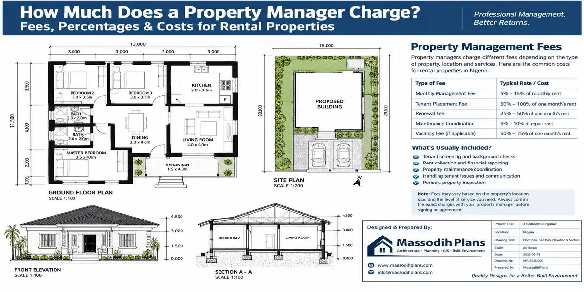
Everything you need to understand, choose, design, draw and prepare a house plan from an empty plot to a complete set of building drawings.
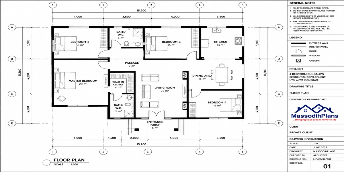
House Plans: Complete Guide to Floor Plans, Building Drawings, Home Designs
Introduction
I still remember the first time a client handed me a folded piece of paper and said, “Massodih, is this even a house plan?” It was a single, messy sketch no dimensions, no elevations, nothing a builder could actually use. That moment, years ago, taught me something I have carried through every project since: most people are not confused because they are careless. They are confused because nobody has ever sat down and explained house plans to them in plain, honest language.
That’ is exactly what this guide is for.
Whether you are a student or building your first home in Lagos, Toronto, Sydney, London, or anywhere else in the world, you are likely carrying the same questions I have answered thousands of times across a desk, a phone call, or a video screen: What exactly is a house plan? What do all these lines and symbols actually mean? How do I know if my plan is good, or my plot is even big enough?
I have spent this entire guide answering those questions the way I would for a friend sitting across from me not with jargon, not with fluff, but with real experience from real projects, real mistakes I have corrected, and real families I have helped house.
Forty-five sections. No shortcuts. No trends chased. Just everything I genuinely wish every student and client understood before construction begins.
Let’s start from the very beginning.
Quick Summary: Everything This Guide Covers
A house plan is the complete set of drawings floor plans, elevations, sections, foundation, roof, electrical, and plumbing layouts that shows exactly how a home will be built before construction begins. In this guide, I will take you through what a house plan actually contains, how to read and design one yourself, how plans differ by bedroom count, building type, floor count, plot size, and architectural style, and how to actually draft each drawing from floor plans to elevations, sections, roof plans, electrical, and plumbing layouts in AutoCAD.
You’ll also learn how to choose the right plan for your family, avoid the most common house-plan mistakes, understand what a plan costs in your specific country, and know exactly when you legally need an architect or engineer. Real case studies from my own years of practice show this process in action, and a full FAQ answers the questions people search for most.
Whatever stage you are at buying land, comparing plans, or ready to build this guide gives you everything you need to move forward with genuine confidence.
What Is a House Plan?
Definition of a House Plan
A house plan is the full set of drawings that shows exactly how your home will be built, before any construction starts. It shows room sizes, door and window positions, wall layout, roof shape, and how water and electricity will move through the house. Think of it as a recipe every measurement and material is written down so nothing is left to guesswork. A good house plan protects your money, your time, and your safety. Without one, builders make decisions on-site, and that’s where costly mistakes usually begin.
House Plan vs Floor Plan
A floor plan is only one piece of a full house plan. It’s the top-down view of a single level, showing rooms, walls, and doors nothing about the roof, foundation, or wiring. A house plan is the complete package: floor plans plus elevations, sections, electrical layout, plumbing layout, and structural details. So when someone shows you just one drawing of room layouts, that’s a floor plan. When you get everything needed to actually build, that’s the full house plan.
House Plan vs Building Plan
These two are close, and many people use them interchangeably, which is fine in everyday conversation. Technically, “building plan” is the wider term it can describe drawings for any structure: a house, an office, a warehouse, a church. “House plan” narrows that down specifically to a residential home. So every house plan is a type of building plan, but not every building plan is a house plan. Your local permit office may use “building plan” on official documents even when it’s clearly a home.
House Plan vs Blueprint
“Blueprint” is an older term from decades ago, when architectural drawings were copied using a process that turned the paper blue with white lines. That’s literally where the word comes from. Today, nobody prints blue paper anymore plans come as digital PDFs, CAD files, or printed sheets in normal black and white. But the word stuck around, so people still say “blueprint” to mean house plan. Same idea, different era of technology.
Architectural Drawing vs Construction Drawing
An architectural drawing focuses on design how the house looks, feels, and flows. It’s what you review with your architect to fall in love with the design. A construction drawing (also called a working drawing) goes further it carries the technical detail your builder needs on-site: exact beam sizes, foundation depth, wall thickness, wiring routes. Architectural drawings sell the dream; construction drawings build the house. You need both, but the builder lives and breathes the second one daily.
Working Drawings
Working drawings are the detailed, technical drawings contractors actually use during construction. They include precise measurements, structural details, material specifications, and notes that guide every trade masons, electricians, plumbers, carpenters. If architectural drawings are the “vision,” working drawings are the “instruction manual” on-site. I always tell clients: never let a builder start without proper working drawings in hand it’s the single biggest cause of construction disputes and budget overruns I have seen in years of practice.
What a Complete House-Plan Package Contains
From my experience handling projects across South-South Nigeria and beyond, a complete package always includes: site plan, floor plans for every level, elevations (front, side, rear), sections showing height and structure, roof plan, electrical layout, plumbing layout, foundation plan, and a material specification list. Missing any one of these creates gaps, gaps that builders fill with guesswork, and guesswork is where budgets and timelines quietly fall apart.
Why a House Plan Is Necessary Before Construction
Building without a proper plan is like driving to a new city with no map you’ll get somewhere, just not where you intended, and it’ll cost more fuel and time. A house plan prevents wrong room sizes, wasted materials, structural weaknesses, and permit rejections. I’ve seen families abroad save tens of thousands of dollars simply by finalizing their plan properly before breaking ground. It’s the cheapest insurance you’ll ever buy in the entire building process.
Who Uses House Plans
House plans aren’t just for architects. Homeowners use them to visualize and approve their future home. Contractors and builders use them daily on-site to construct correctly. Structural and services engineers use them to confirm safety and systems. Local government and building authorities use them to approve permits. Even mortgage lenders sometimes request them before releasing funds. Everyone involved in getting a house from idea to reality relies on the same set of drawings to stay aligned. See our House plans Library
What Does a Complete House Plan Include?
This is where many people get confused. They think a “house plan” is just one drawing showing rooms. In my years of practice, I’ve had to explain to countless students and clients from first-time homeowners to diaspora families building from abroad that a real, buildable house plan is actually a full set of drawings working together. Miss even one, and your builder is left guessing. Let’s go through every drawing that belongs in a complete package.
1. Site Plan
This shows your house sitting on your land plot boundaries, setbacks, driveway, and how the building relates to the street and neighboring plots. It’s the first drawing any approval authority checks.
2. Floor Plan
The top-down view of each level, showing rooms, walls, doors, and how space flows from one area to another. This is usually the drawing people fall in love with first.
3. Foundation Plan
Shows what sits underground footing sizes, depth, and layout. Get this wrong and everything above ground suffers, no matter how beautiful the design looks.
4. Roof Plan
Shows roof shape, slope, and drainage direction. It tells the roofer exactly how to cut and lay materials, and how rainwater will exit the building safely.
5. Front Elevation
The view of your house from the street the “first impression” drawing. This is what most homeowners show off to family and friends.
6. Rear Elevation
The back view of the house. Often overlooked, but just as important for windows, balconies, or extensions at the back.
7. Left Elevation
Side view from the left. It reveals how the house looks from that angle and how it fits your specific plot.
8. Right Elevation
Side view from the right, completing the full external picture of your home from all four directions.
9. Building Sections
A “cut-through” view showing floor-to-floor heights, roof pitch, and internal structure. This is where hidden details like ceiling height finally become clear.
10. Electrical Layout
Shows wiring routes, panel location, and circuit paths. A good electrical layout prevents dangerous last-minute wiring decisions during construction.
11. Lighting Layout
A separate drawing showing exactly where every light fixture goes ceiling lights, wall lights, outdoor lighting matched to how each room will actually be used.
12. Power/Socket Layout
Shows every socket and switch position. I always tell clients: plan your sockets around your furniture, not the other way around, or you’ll be using extension cords for years.
13. Plumbing Layout
Shows pipe routes for water and waste inside the house bathrooms, kitchen, laundry. Poor plumbing layout is one of the most expensive things to fix after construction.
14. Water Supply Layout
Shows how clean water enters and travels through the home, including tank position, pump location, and pipe sizing critical in areas with irregular water pressure.
15. Drainage Layout
Shows how wastewater and rainwater leave the property safely, connecting to septic systems, soak-aways, or municipal drains depending on your location.
16. Door Schedule
A simple table listing every door in the house size, type, and material. It keeps ordering accurate and avoids the classic “wrong size door” site mistake.
17. Window Schedule
Same idea as the door schedule, but for windows size, type, and glazing. This helps with accurate quotes and faster procurement before construction begins.
18. Ceiling Plan
Shows ceiling design, levels, and finishes especially important for homes with drop ceilings, exposed beams, or decorative treatments.
19. Staircase Details
A detailed drawing of stair dimensions, step height, tread depth, and railing design. Staircases built without proper details are a common safety hazard I’ve had to correct on-site.
20. Structural Drawings
Prepared by a structural engineer, these show beam sizes, column positions, and reinforcement details that keep your home standing safely for generations.
21. Construction Details
Close-up drawings of tricky junctions how a wall meets a roof, how a window frame is fixed. These small details prevent big problems like leaks and cracks.
22. General Notes
Written instructions covering standards, tolerances, and site rules that don’t fit neatly into a drawing but matter enormously on-site.
23. Schedules and Specifications
A final master list of materials, finishes, and quantities paint types, flooring, tiles, fittings so your builder orders exactly what your design calls for, nothing more, nothing less.
As you can see, a real house plan is a team of drawings, not a single sheet. Every drawing above talks to the others your electrical layout depends on your floor plan, your foundation plan depends on your structural drawings, and so on. This is exactly why, in my practice, I never release a floor plan alone and call it “complete.” If you want to see what a properly packaged plan set looks like in real life, our Plans Library has full examples you can study. In the next Section, we’ll look at Types of House Plans by Number of Bedrooms.
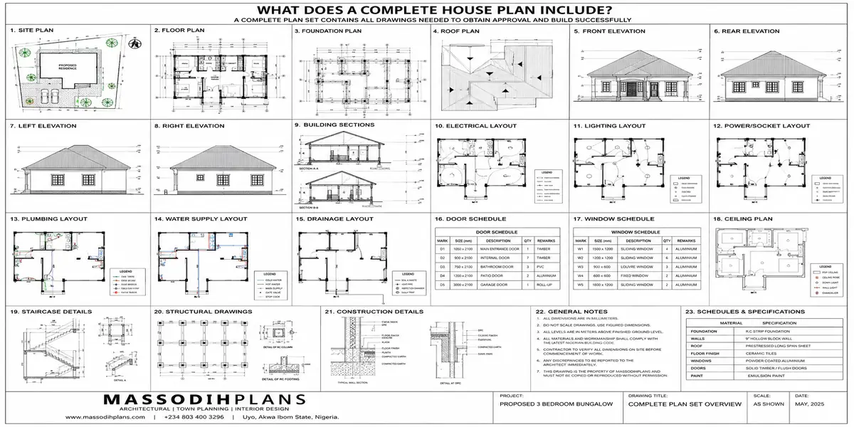
What a complete house plan includes
Types of House Plans by Number of Bedrooms
Bedroom count is usually the first thing people search for, so let’s break it down properly from small starter homes to large family houses.
1 Bedroom House Plans
Perfect for singles, young couples, or retirees wanting less to clean and maintain. Compact, affordable to build, and cheaper to heat or cool. I always recommend these to clients wanting a first home without financial strain.
2 Bedroom House Plans
A favorite for small families or couples expecting their first child. Gives you a guest room or home office option without adding much construction cost. Explore full designs in our 2 Bedroom House Plans article.
3 Bedroom House Plans
The most popular size worldwide, and for good reason it balances space, cost, and resale value beautifully. Ideal for growing families. Browse real examples in our 3 Bedroom House Plans guide.
4 Bedroom House Plans
Great for larger families or households needing a dedicated study or home gym. I’ve designed many of these for clients who work remotely and need separate quiet spaces. See our 4 Bedroom House Plans selection.
5 Bedroom House Plans
Suited to multigenerational families or households that entertain often. Gives room for extended family visits without sacrificing privacy. Check our 5 Bedroom House Plans catalog.
6 Bedroom House Plans
Common among larger extended families or those planning future rental income from spare rooms. Requires careful zoning and plot size planning.
7+ Bedroom House Plans
Typically custom-built for large family compounds, boarding arrangements, or high-end estate living. These need serious structural and cost planning from the start.
Guest-Room House Plans
Designed with a separate, self-contained guest suite its own entrance, bathroom, and privacy. Ideal for families who host often or want rental flexibility.
Multiple-Master-Bedroom Plans
Houses with two or more en-suite master bedrooms, popular with multigenerational households or co-owned properties. I’ve designed several for siblings building together on one plot.
Whatever your family size today, plan a little ahead life changes faster than most people expect. In the next Section, we’ll look at Types of House Plans by Building Type.
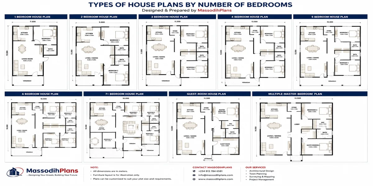
Types of House Plans by Number of Bedrooms
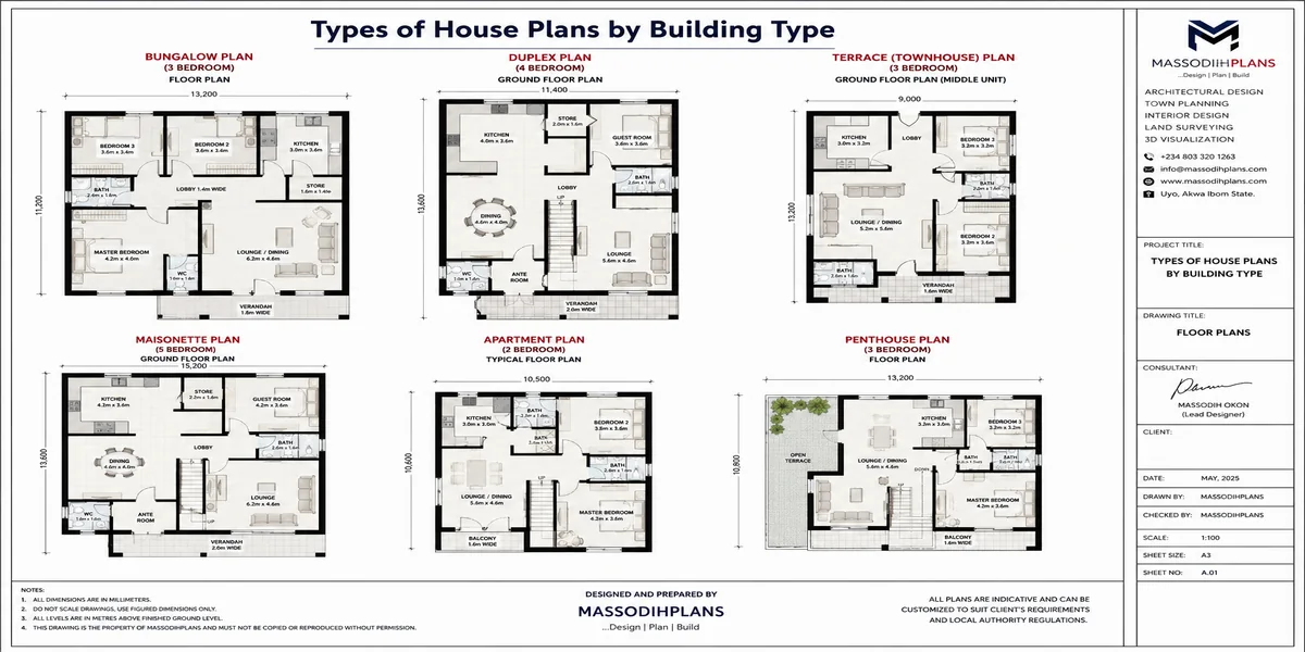
Types of House Plans by Building Type
Beyond bedroom count, the type of building you choose shapes your budget, privacy, and future flexibility. Let me take you through each one, the way I would with a student and or client deciding what actually fits their land and lifestyle.
Self-Contained House Plans
A self-contained unit has everything one household needs in one enclosed space bedroom, bathroom, kitchenette, all under one roof with no shared spaces. Popular for singles, students, or as a rental unit on a larger property. See our Self-Contained House Plans collection.
Bungalow House Plans
Single-storey homes with no stairs, making them ideal for elderly residents or families who simply prefer everything on one level. Easier and often cheaper to build too. Explore our Bungalow House Plans.
Duplex House Plans
Two separate living units, either side-by-side or stacked, sharing one building structure. Great for rental income or housing extended family while keeping full privacy. Check our Duplex House Plans guide.
Detached House Plans
A standalone house with no shared walls at all. Gives maximum privacy and freedom to design all four sides freely. Most families dream of this first.
Semi-Detached House Plans
Two homes sharing one common wall, each with its own separate entrance and yard. A smart way to reduce construction cost while keeping decent privacy.
Terrace House Plans
A row of connected homes sharing walls on both sides, common in tighter urban plots. Efficient use of land, especially valuable in cities where space is limited.
Townhouse Plans
Multi-storey homes sharing side walls, usually with a private entrance and small yard or balcony. Popular in the US, UK, and Canada for urban and suburban living.
Apartment Plans
Individual units within a larger shared building, usually with shared entrances, hallways, and sometimes amenities. Ideal for high-density living.
Multi-Family House Plans
A single structure designed to house more than one family unit, each with independent living spaces. Excellent for investment properties or extended family arrangements.
2-Unit Plans
Two independent living units in one building think of it as the simplest multi-family setup, perfect for a starter rental property or intergenerational living.
3-Unit Plans
Three separate units under one roof, balancing rental income potential with manageable construction cost. A step up for investors ready to scale.
4-Unit Plans
Four independent units, often called a fourplex a strong entry point into serious rental income while still being manageable to maintain.
Block of Flats
A larger building with multiple apartment units, common in cities across Nigeria, the UK, and beyond. Requires careful structural and utility planning from day one.
Guest House Plans
A smaller, separate structure built alongside a main home for visitors gives guests privacy while keeping them close. I design these often for clients who host extended family regularly.
Boys’ Quarters/Annex Plans
A compact additional structure, traditionally used for staff or extended family, now often repurposed as a home office or private studio.
Garage Apartment Plans
A living unit built above or beside a garage smart use of otherwise wasted space, and a great option for rental income or a private in-law suite.
Granny-Flat/ADU-Type Plans
A small, self-contained secondary home on the same plot as your main house hugely popular right now in the US, Australia, and Canada for aging parents or rental income.
Choosing the right building type early saves you from redesigning halfway through the process I’ve seen it happen, and it’s always more expensive than getting it right from the start. In the next Section, we’ll explore House Plans by Number of Floors. See our Duplex House Plans collection
Types of House Plans by Building Type
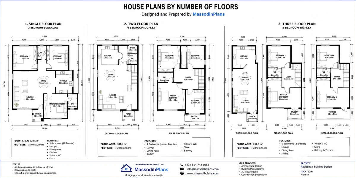
House Plans by Number of Floors
How many floors you build affects cost, land use, and daily living comfort. Let’s go through the options I discuss with clients every week.
Single-Storey House Plans
Everything on one level no stairs, easier movement, and simpler construction. A favorite for families with young children or elderly members.
1-Storey Bungalow
Technically a single-storey home, but designed with that classic low, wide bungalow character spacious rooms, often with a veranda.
2-Storey House Plans
The most popular choice for growing families needing more space without buying a bigger plot. Bedrooms upstairs, living spaces downstairs a layout I design constantly.
3-Storey House Plans
Ideal for narrow urban plots where you build up instead of out. Requires careful staircase and structural planning early in the design.
Split-Level House Plans
Floors are staggered by half-levels instead of full storeys, creating natural separation between living and private areas. A clever design for sloped land.
Basement House Plans
Adds usable space below ground storage, extra rooms, or even a rental unit. Very common in the US, Canada, and parts of Europe. Explore our Basement House Plans.
Houses With Attic
Uses the roof space as an extra room instead of wasted air above the ceiling great for storage, a study, or a cozy bedroom.
Houses With Mezzanine
A raised platform level within a tall room, often overlooking the space below. Popular in modern, open-plan designs I’ve done for younger clients.
Duplexes
As covered earlier, duplexes stack or split two units vertically or side-by-side a floor arrangement worth revisiting here for its space efficiency. See our Duplex House Plans.
Multi-Storey Apartment Buildings
Several floors of stacked residential units, needing strong structural design, proper fire safety, and elevator access depending on height.
The right floor count always depends on your plot size, budget, and family needs never just personal preference alone. In the next Section, we’ll look at House Plans by Plot/Land Size.
House Plans by Number of Floors
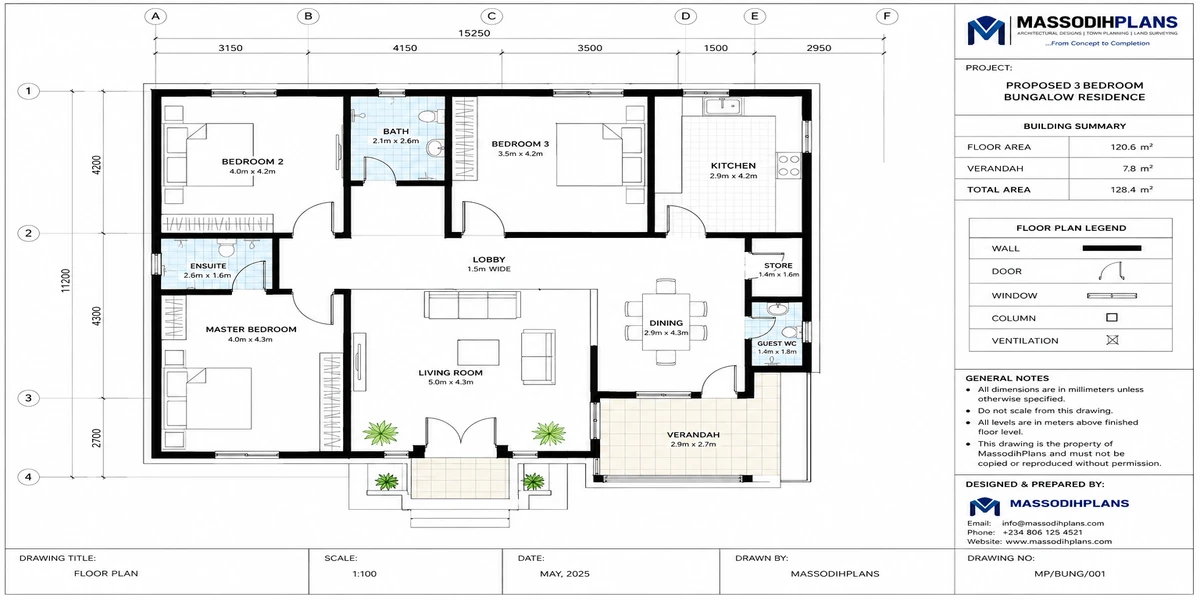
House Plans by Plot/Land Size
This is one of the most practical sections in the entire article, because the truth is: your plot size decides your design more than any style photo ever will. I’ve had clients fall in love with a plan online, only to realize it simply won’t fit their land. Let’s fix that thinking here.
House Plans for Small Plots
Small plots demand smart, compact design vertical building, open-plan living, and minimal wasted circulation space. Every square foot must earn its place.
30×50 Plots
A common size in many residential layouts. Works well for a modest 2 or 3 bedroom bungalow, or a compact 2-storey home if you need more rooms without expanding the footprint.
40×50 Plots
Slightly more breathing room than 30×50, giving you space for a small garden, driveway, and a comfortable 3 bedroom design without feeling cramped.
40×60 Plots
A very flexible size enough room for a proper compound feel, side setbacks, and even a small guest area or boys’ quarters alongside the main house.
50×50 Plots
A square plot, which actually challenges designers more than people expect. It suits centrally-planned layouts with rooms arranged around a courtyard or central hallway.
50×100 Plots
A generous size that opens up real design freedom larger living areas, multiple bedrooms, garden space, and often room for future expansion.
60×100 Plots
Ideal for larger family homes, duplexes, or even small multi-unit developments, with enough land left for parking and outdoor living space.
Narrow Plots
Common in dense urban areas. The solution is almost always to build upward rather than outward, using 2 or 3 storeys with a tight, efficient footprint.
Wide Plots
Give you the freedom to spread the design horizontally bungalows with wide frontages, wraparound verandas, or side extensions become realistic options here.
Corner Plots
These border two streets instead of one, which affects setback rules and privacy planning. I always design corner plots with careful attention to which side faces which street.
Irregular Plots
Not every plot is a perfect rectangle. Irregular shapes need custom floor plans that work with the land’s natural boundaries instead of forcing a standard design onto it.
Deep/Narrow Lots
Long and thin, these plots benefit from a linear layout rooms arranged in a sequence from front to back, often with a central corridor or courtyard for light.
Sloping Plots
Sloped land can actually become a design advantage think split-level homes or basement integration but it needs proper engineering assessment before any drawing begins.
Corner Lots
Similar considerations to corner plots above extra visibility from two sides means your design should look intentional and finished from every angle, not just the front.
Urban Plots
Typically smaller and surrounded closely by neighbors, demanding thoughtful privacy planning, smart window placement, and efficient vertical use of space.
Here’s the real lesson from my years of practice: the exact same house design can almost always be redesigned to fit a different plot. A 3 bedroom bungalow meant for 50×100 can be reworked into a 2-storey version for a 30×50 plot, keeping the same room count and family needs but adjusting the footprint and height. This is why I always tell clients don’t fall in love with a picture before checking if it truly fits your land. Get your plot dimensions confirmed first, then let the design follow the land, not the other way around. We will cover House Plans by Floor Area in the next section. If you designing for small plots see it here.
House Plans by Plot/Land Size
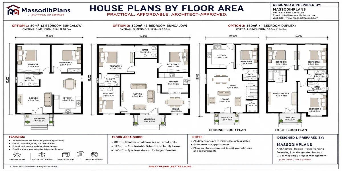
House Plans by Floor Area
Floor area is one of the most honest ways to plan a budget, because square footage connects directly to material cost, construction time, and long-term maintenance. Let’s walk through the ranges I work with most often.
Under 500 sq ft
Perfect for a compact studio or single-person home. Every inch is planned carefully usually a combined living and sleeping area, small kitchen, and bathroom. Affordable to build and maintain.
500–1,000 sq ft
A comfortable size for a 1 or small 2 bedroom home. Enough space for a proper living room, kitchen, and one or two bedrooms without excess.
1,000–1,500 sq ft
A common sweet spot for small families. Typically fits a 2 or 3 bedroom layout with separate living and dining areas, plus a functional kitchen.
1,500–2,000 sq ft
Gives real breathing room a proper 3 bedroom home with more generous room sizes, maybe a home office corner, and better circulation space between rooms.
2,000–2,500 sq ft
This range usually supports a solid 4 bedroom design, often with an en-suite master bedroom, a family lounge separate from the main living room, and a larger kitchen.
2,500–3,000 sq ft
Comfortable territory for larger families 4 to 5 bedrooms, multiple bathrooms, and dedicated spaces like a study or entertainment room become realistic here.
3,000–4,000 sq ft
Homes at this size start feeling like proper family estates 5+ bedrooms, larger common areas, guest suites, and sometimes a second living room or family lounge upstairs.
4,000+ sq ft
Large, spacious homes suited to big families, frequent entertaining, or households wanting serious separation between private and shared spaces. Construction and maintenance costs rise significantly here, so proper planning matters even more.
Luxury Homes
Beyond just square footage, luxury homes focus on quality premium finishes, custom joinery, high ceilings, and often unique architectural features designed specifically for the client, not copied from a catalog.
Mansions
The largest scale of residential design expansive floor areas, multiple wings, extensive outdoor spaces, and often supporting structures like guest houses or staff quarters. These require serious structural, mechanical, and cost planning from the very first sketch.
Here’s something I always tell clients before they fix their mind on a square footage number: bigger isn’t automatically better. I’ve designed 1,200 sq ft homes that felt more spacious and comfortable than poorly planned 2,500 sq ft homes, simply because the layout made sense: good flow, good light, no wasted corridors. Floor area should match your actual family size and lifestyle, not just your budget ceiling or what a neighbor built. Get the layout right first, then let the square footage follow the real need. The most important section we will look at below is House Plans by Architectural Style. Also See our guide to floor area and budget
House Plans by Floor Area
House Plans by Architectural Style
Style is where a house stops being just a shelter and starts telling a story about the people who live in it. Over the years, I’ve designed across many styles for clients both locally and abroad here’s an honest breakdown of each.
Modern
Clean lines, flat or low-pitched roofs, large windows, and minimal ornamentation. Function leads the design, with open floor plans and lots of natural light.
Contemporary
Often confused with modern, but contemporary simply means “current” it evolves with today’s trends, mixing materials like glass, steel, and wood freely without sticking to one fixed rule.
Traditional
Classic layouts, symmetrical facades, and familiar rooflines that don’t chase trends. Traditional homes age gracefully and rarely look “out of date.”
Minimalist
Stripped down to the essentials simple forms, neutral colors, and a strong focus on space and light over decoration. “Less is more” isn’t just a phrase here; it’s the whole philosophy.
Mediterranean
Warm stucco walls, terracotta roof tiles, arched doorways, and courtyard-style layouts inspired by Southern Europe. Works beautifully in warm climates.
Colonial
Symmetrical, formal facades with evenly spaced windows and a centered front door a classic style still loved across the US and UK.
Craftsman
Known for exposed wood beams, covered porches, and handcrafted details. Feels warm and personal, popular in North America.
Farmhouse
Simple, functional design with gabled roofs, wide porches, and a relaxed, welcoming feel rooted in rural building traditions.
Modern Farmhouse
Takes the farmhouse charm and blends it with clean modern lines and larger windows currently one of the most requested styles among my international clients.
Ranch
Single-storey, wide and low, with an open layout and easy indoor-outdoor flow. Practical and popular for families wanting everything on one level.
Cottage
Cozy, smaller-scale homes with steep roofs and charming details. Feels intimate and personal, often associated with countryside living.
Cape Cod
Simple, symmetrical New England-style homes with steep roofs and central chimneys built originally to handle cold, snowy climates.
Victorian
Ornate detailing, steep roofs, decorative trim, and bold colors. A style that stands out and carries real historical character.
Neoclassical
Grand columns, symmetrical facades, and design inspired by ancient Greek and Roman architecture often chosen for larger, statement homes.
Tropical
Designed for hot, humid climates wide overhangs, high ceilings, and lots of ventilation to keep the home cool naturally without heavy reliance on air conditioning.
African Contemporary
Blends modern building techniques with African design sensibility bold forms, courtyard layouts, and materials chosen to suit the local climate and culture.
Modern Nigerian
A style I work with constantly combines contemporary layouts and finishes with practical adaptations for Nigerian weather, power realities, and family living patterns.
Traditional Nigerian-Inspired
Draws from local building heritage courtyard arrangements, raised foundations, and roof designs suited to heavy rainfall, reimagined with today’s materials and standards.
Here’s what I always tell clients before they pick a style: choose what fits your climate and lifestyle first, then let personal taste guide the details. A Mediterranean-style home with a flat roof in a heavy-rain climate will cause you nothing but leak problems, no matter how beautiful it looks in photos. Style should work with your environment, not against it that’s the difference between a house that looks good in a magazine and one that actually serves your family well for decades. Let show you How to Choose the Right House Plan. Modern Nigerian house plan designs.
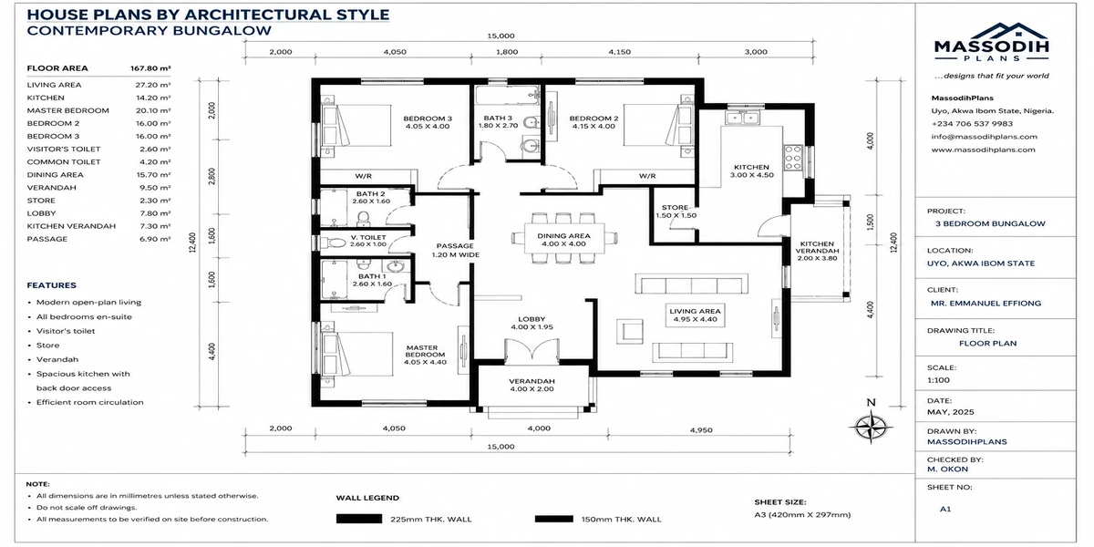
House Plans by Architectural Style
How to Choose the Right House Plan
This is the question I get asked more than any other: “Massodih, how do I know which plan is right for me?” After years of guiding clients through this exact decision, let me take you through it the same way I would in a real consultation.
Number of Occupants and Family Size
Start here, always. Count everyone who will actually live in the home not just today, but realistically in the next 5 to 10 years. A young couple planning children needs different bedroom counts than a retired couple downsizing.
Budget
Be honest with yourself about what you can truly afford, including a buffer of at least 15-20% for unexpected costs. I’ve seen too many families start a beautiful design they couldn’t finish, and an unfinished house costs more in the long run than a smaller, completed one.
Plot Dimensions and Setbacks
As we covered in Section 6, your plot size and shape determine what’s realistically possible. Setbacks the required distance between your building and plot boundaries often reduce your usable footprint more than people expect, so confirm these early with your local authority.
Number of Bedrooms and Bathrooms
Match bedrooms to your family size plus a little extra for guests or future needs. For bathrooms, a good rule I use: at least one full bathroom per two bedrooms, plus a guest powder room if space allows.
Parking Requirements
Think about how many vehicles your household actually has or will have, and whether visitors will need space too. Don’t squeeze parking in as an afterthought it affects your entire site layout.
Future Expansion
Choose a design that allows adding a room or floor later without demolishing existing work. I always sketch a “phase two” option for clients building on a budget, so today’s small home can grow properly tomorrow.
Privacy
Consider window placement, room positioning, and outdoor sightlines from neighboring properties. Bedrooms and bathrooms especially need thoughtful placement away from public view.
Natural Ventilation and Lighting
A well-ventilated, well-lit home reduces your dependence on air conditioning and artificial lighting saving real money over the years. Cross-ventilation (windows on opposite walls) is one of the simplest, most effective design principles I insist on.
Circulation
This means how easily people move through the house hallways, doorways, and room connections. Poor circulation creates a home that feels cramped even when it’s technically spacious.
Storage
Closets, pantries, and utility spaces are often the first thing sacrificed in a design, and the first thing clients regret losing. Always plan generous storage from the start, not as an afterthought.
Outdoor Space
Gardens, verandas, and patios extend your living space and add real quality of life. Even small plots can include a modest outdoor corner with the right layout.
Accessibility
Consider wheelchair access, wider doorways, and step-free entries especially important if elderly family members live with you now or might in the future. It’s far easier to plan this in than to retrofit later.
Climate
Your local weather should shape roof pitch, window sizing, wall materials, and ventilation strategy. A design that works beautifully in a dry climate can fail badly in a wet or humid one.
Local Regulations
Every location has its own building codes, height restrictions, and approval requirements. Always confirm these with your local planning authority before finalizing any design this single step prevents costly redesigns later.
Construction Complexity
Some designs, especially those with unusual angles or many levels, cost significantly more to build than simpler forms. Ask your architect honestly about the complexity-to-cost ratio before falling in love with an elaborate design.
Here’s my honest advice: don’t choose a house plan based on how it looks in a photo alone. Walk through each of these factors deliberately, the way we just did. The right plan isn’t the most beautiful one it’s the one that truly fits your family, your land, your climate, and your budget, all at once. Get that balance right, and you’ll build a home you’re genuinely happy living in for decades, not just a house that looked good on the day it was finished. Let me also show you How to Read a House Floor Plan in the next section below. See our House Plan Buyer’s Checklist
How to Read a House Floor Plan
If you’ve ever stared at a floor plan and felt completely lost you’re not alone. Almost every client I’ve worked with, from first-time homeowners to seasoned property investors, needed help reading their first plan. Once you understand the basic symbols, though, it becomes second nature. Let me teach you the way I teach my own students and clients, symbol by symbol.
Walls
Walls appear as thick, solid lines or double parallel lines with shading or hatching between them. Exterior walls are usually drawn thicker than interior partition walls, because they carry more structural weight and insulation.
Doors
A door is shown as a break in the wall line with a curved arc that arc shows the direction and swing path of the door when it opens. The straight line is the door itself; the curve just shows you which way it moves.
Windows
Windows appear as a thin break in the wall line, often shown with two or three parallel lines within the opening. Unlike doors, windows don’t have a swing arc since they don’t open into the room space the same way.
Dimensions
These are the small numbers with arrows or tick marks along the edges of walls and rooms, showing exact measurements in feet, meters, or millimeters. Always check the unit being used mixing feet and meters is a mistake I’ve seen cause real construction errors.
Room Labels
Simple text inside each room telling you its purpose “Living Room,” “Bedroom 2,” “Kitchen.” Sometimes the labels include the room’s square footage too, which helps you judge scale at a glance.
Furniture Symbols
Beds, sofas, tables, and kitchen counters are often drawn as simplified outlines to help you visualize how the space will actually be used once furnished not just as empty rooms.
Stair Symbols
Stairs are shown as a series of parallel lines representing each step, usually with an arrow indicating the direction of travel “UP” or “DOWN” and sometimes a break line if the staircase continues beyond the current floor’s view.
Section Indicators
These look like a straight line with arrows or triangle markers cutting through the plan, labeled with letters like “A-A” or “B-B.” They tell you exactly where the building has been “sliced” to create a section drawing elsewhere in your plan set.
Elevation Indicators
Small triangular symbols usually placed at the edges of the plan, pointing outward and labeled (North, South, East, West, or Front, Rear, Left, Right). They tell you which elevation drawing corresponds to which side of the building.
Grid Lines
Numbered or lettered reference lines running across the plan, used mainly by engineers and contractors to pinpoint exact structural positions think of them like coordinates on a map for your house.
North Arrow
A simple arrow symbol, usually in a corner of the site plan or floor plan, showing which direction is true north. This matters enormously for sunlight planning and orientation.
Scale
Every proper plan states its scale, like “1:100” or “1/4 inch = 1 foot,” telling you how the drawing size relates to real-world size. Never assume a plan is “true to size” on your screen or printout without checking this.
Levels
Small numbers, often with a symbol like a triangle or circle, indicating floor heights relative to a fixed reference point critical for sloped plots or multi-storey homes where different areas sit at different heights.
Structural Elements
Columns, beams, and load-bearing walls are usually shown as solid black squares or rectangles, sometimes with hatching. These are not decorative never remove or shift them without an engineer’s input.
Plumbing Symbols
Simple icons represent sinks, toilets, showers, and bathtubs, often paired with pipe lines showing water supply and drainage routes. Bathroom and kitchen areas usually carry the most plumbing symbols on any plan.
Electrical Symbols
Circles with lines represent light fixtures, small squares or specific icons represent sockets, and switch symbols are usually shown near doorways, connected to their corresponding light with a dashed line.
Putting It All Together: A Real Annotated Example
Let me take you through a simple 3 bedroom bungalow floor plan the way I would with a client in my office. Starting at the entrance, you’d see a door symbol with its swing arc opening inward into a labeled “Living Room.” Dimension lines along the outer wall might read 12ft x 15ft, telling you the room’s exact size. Moving through an interior doorway, you’d reach a hallway with grid lines running along the structural columns, guiding you toward three bedrooms, each labeled clearly with furniture symbols showing bed placement. In the kitchen, you’d spot plumbing symbols near the sink and electrical symbols marking socket positions along the counter practical details that tell you exactly how daily life will function in that space, long before construction begins. Avoiding common floor plan mistakes. Here is it:
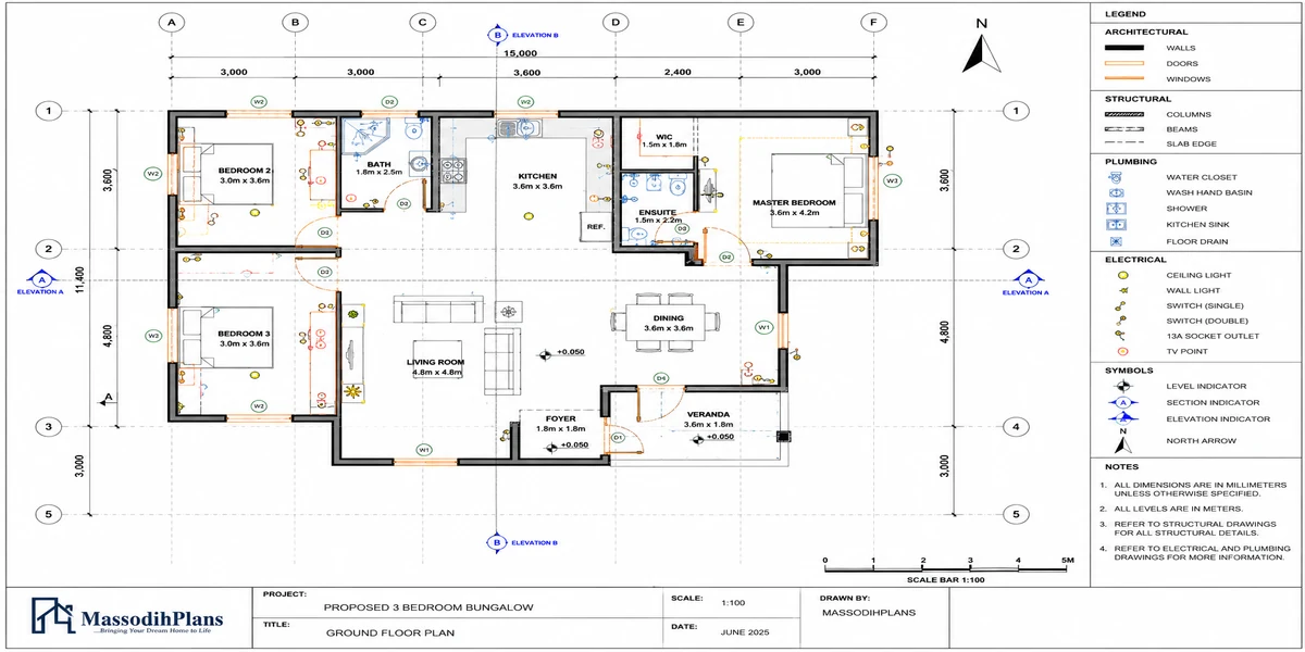
How to Read a House Floor Plan
This is exactly the kind of hands-on walkthrough I go through with every student and client before we finalize their working drawings, because a floor plan you can actually read is a floor plan you can trust.
If you want to practice this skill further, our article on understanding house plan drawings before construction goes even deeper into interpreting full plan sets, and our guide to common floor plan mistakes homeowners make shows you real examples of what happens when these symbols get misunderstood on-site.
Once you’re comfortable reading a floor plan, the next natural step is understanding How to Design a House Floor Plan and get approved by your local building authority which is exactly what we’ll cover in the next Section.
How to Design a House Floor Plan
This is where I want to take you beyond just reading a plan, I want to show you exactly how one gets created in the first place. This is the actual process I follow in my office in Uyo for every single student I trained and client, whether they’re building locally or sending instructions from abroad. Let’s walk through it step by step, using a real example: a young couple who came to me wanting a 3 bedroom bungalow on a 50×100 plot.
Step 1: Understand the Client’s Requirements
Everything starts with a conversation, not a drawing. I ask questions: How many people will live here? Do you work from home? Do you entertain often? For this couple, the answers were simple two adults now, planning for one child soon, and a strong need for a home office since the husband worked remotely.
Step 2: Study the Plot
Next, I visit or review the actual land its orientation, slope, soil type, and surroundings. Their plot faced east, which meant morning sun would hit the front of the house first. This single fact would later shape where I placed the living room windows.
Step 3: Determine Setbacks
Before drawing anything, I confirm the required distance between the building and each plot boundary, based on local regulations. Their setbacks left us a usable footprint of roughly 40×70 feet out of the full 50×100 plot a detail that changes everything about what’s realistically possible.
Step 4: Establish Building Footprint
With setbacks confirmed, I sketch the outer boundary of the house itself a simple rectangle or shape representing the maximum area we can build within. Think of this as drawing the outline before filling in any rooms.
Step 5: Create Room Schedule
Now I list every room the house needs: living room, dining area, kitchen, 3 bedrooms, 2 bathrooms, a home office, and storage. This becomes my checklist for the entire design nothing gets left out by accident.
Step 6: Determine Room Sizes
Each room on that list gets an appropriate size based on function and comfort. A master bedroom might need 14×16 ft, while a standard bedroom works well at 12×12 ft. I never guess these numbers years of practice have taught me realistic, comfortable dimensions for each room type.
Step 7: Arrange Spaces
This is where real design skill comes in. I group rooms by function public spaces like the living and dining area near the entrance, private spaces like bedrooms toward the back or upper level, and service areas like the kitchen positioned for easy access to both dining and outdoor space.
Step 8: Establish Circulation
I draw the “paths” people will walk through the house daily from the front door to the living room, from bedrooms to bathrooms, from kitchen to dining. Good circulation means short, sensible paths with no wasted hallway space and no room you have to walk through just to reach another.
Step 9: Position Doors and Windows
With rooms arranged and circulation mapped, I place doors where movement naturally flows and windows where they’ll capture the best light and airflow. Remember that east-facing plot? I positioned the living room’s main windows to catch that gentle morning sun, while placing bedroom windows on the west side to avoid harsh afternoon heat.
Step 10: Add Furniture
I sketch basic furniture into each room beds, sofas, dining tables to test whether the space actually works in real life, not just on paper. This step catches mistakes early. In this project, we discovered the first kitchen layout didn’t leave enough counter space once appliances were placed, so we adjusted it right there.
Step 11: Check Ventilation
I trace airflow through the house, checking that windows on opposite or adjacent walls allow cross-ventilation. Every room ideally needs at least two openings this couple’s home office initially had only one window, so I added a second on an adjacent wall to keep it comfortable without relying on air conditioning all day.
Step 12: Check Natural Lighting
Similarly, I verify that every room gets adequate daylight, especially spaces where people spend long hours. The home office benefited hugely from that added second window, turning it from a dim box into a genuinely pleasant workspace.
Step 13: Check Dimensions
Now I go back through every room with a careful eye, confirming that stated dimensions match real-world comfort and building standards doorways wide enough, hallways not too narrow, bathrooms with enough clearance to move around fixtures comfortably.
Step 14: Check Functionality
I mentally “walk through” the entire home as if I lived there. Can you carry groceries from the car to the kitchen easily? Can guests use a bathroom without walking through a private area? For this project, we realized the guest bathroom was originally only accessible through the master bedroom hallway an easy fix once caught, a real headache if built that way.
Step 15: Develop the Final Floor Plan
With every check complete, I finalize the drawing clean lines, accurate dimensions, proper labels, and all the symbols we covered in Section 10. This final version becomes the foundation for every other drawing in the full house-plan package: elevations, sections, electrical layout, and more. Working with an architect on your first design.
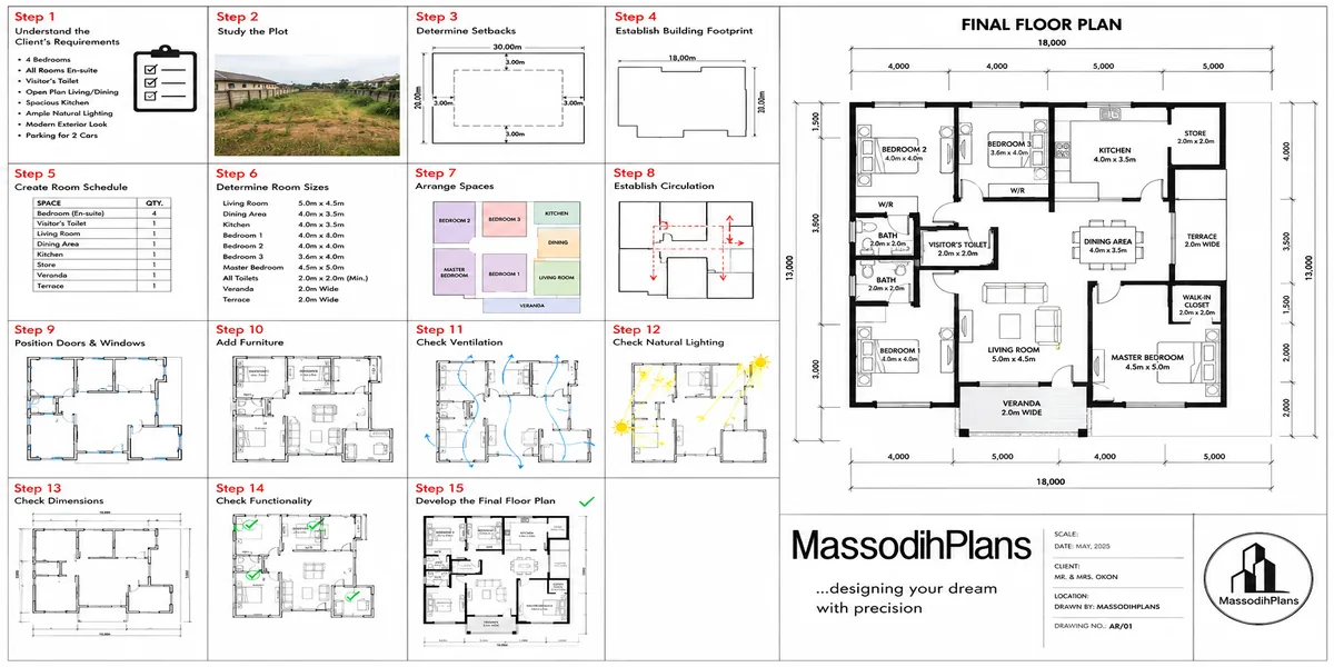
Actual Floor plans design process visually
Seeing the Process, Not Just the Result
What I’ve just walked you through is genuinely how a floor plan comes to life not as a single flash of inspiration, but as fifteen deliberate decisions, each building on the last. When you understand this process, you stop seeing a floor plan as just a pretty drawing and start seeing it as a series of real, practical decisions made on your behalf decisions about your morning sunlight, your daily walking paths, your comfort in every room.
This is exactly the depth I go into with every client, and it’s also why I always tell people: don’t rush this stage. A floor plan finalized in one afternoon rarely holds up to real living. The couple in this example and I went through four full revisions before step 15 and every single revision made the home genuinely better, not just different.
If you’d like to go deeper into any one of these steps, our article on Plan school to avoide costly floor plan mistakes before construction breaks down what happens when steps like circulation and ventilation get skipped, and our guide to working with an architect on your first home design walks you through exactly how this conversation should go from your very first meeting.
In the next section, we’ll move from designing the floor plan to understanding How to Design a 1-Bedroom House Plan, the drawings that show how do drawings without studying architecture.
How to Design a 1-Bedroom House Plan
Let’s put the 15-step process from above into action on a real, small-scale project a 1 bedroom home for a single client I designed for on a compact 30×50 plot.
Requirements
The client needed a private bedroom, a combined living-dining space, a small kitchen, one bathroom, and a compact home office corner a common request among remote workers today. Budget was tight, so every square foot had to justify itself.
Bubble Diagram
Before touching real dimensions, I sketch simple circles (“bubbles”) representing each space, connected by lines showing how they relate. The living area bubble sat closest to the entrance, the kitchen bubble touched the dining bubble, and the bedroom bubble sat furthest back for privacy. This rough map tells me the logic of the house before any walls exist.
Rough Sketch
Next, I translate those bubbles into a loose, hand-drawn layout actual room shapes, roughly proportioned, with doors and windows marked in pencil. At this stage, I’m testing flow, not precision. In this project, my first sketch placed the bathroom too far from the bedroom, so I redrew it closer for practical everyday use.
CAD Drawing
Once the rough sketch feels right, I move into CAD software to draw everything to exact scale real wall thicknesses, accurate room dimensions, properly positioned doors and windows. This is where the design becomes buildable, not just visual. The home office corner, for instance, got a precise 6×7 ft allocation once measured properly in CAD.
Finished Floor Plan
Finally, the drawing gets fully labeled and dimensioned room names, furniture symbols showing a real bed and desk layout, door swings, and window placements all finalized. The result: a tight but genuinely comfortable 480 sq ft home with a private bedroom, functional kitchen, and a bright home office corner that actually gets morning light.
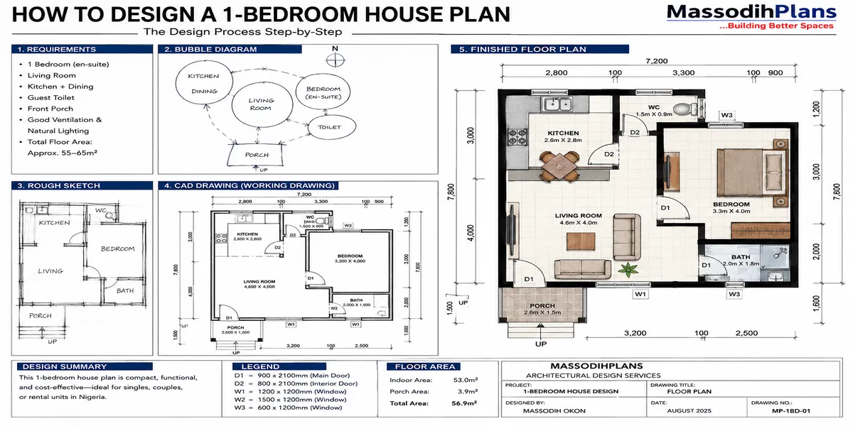
How to design 1 bedroom house plan
This is the same journey every good floor plan takes, no matter the size big houses just repeat this process across more rooms. Small homes actually demand more discipline, because there’s no room to hide a bad decision.
If you’re working with a similarly tight plot, our article on designing efficiently for small plots goes deeper into stretching every square foot without the home feeling cramped.
In the Section below, we’ll apply this same process to a How to Design a 2-Bedroom House Plan, where space allocation gets slightly more complex.
How to Design a 2-Bedroom House Plan
Let’s follow the same process again, this time for a young couple I designed for on a 40×60 plot planning ahead for their first child while keeping a guest room option open.
Requirements
They needed a master bedroom, a second flexible bedroom (nursery now, guest room later), a proper living room separate from dining, a full kitchen, two bathrooms, and covered parking for one car. Unlike the 1 bedroom project, privacy between the two bedrooms mattered here, since one would eventually house a baby needing quiet.
Bubble Diagram
I mapped out bubbles for each space living room bubble near the entrance, dining and kitchen bubbles connected to each other, and the two bedroom bubbles grouped together on the quieter side of the plot, away from street noise. A bathroom bubble sat between the two bedrooms, serving both without needing a separate guest bathroom near the living area.
Rough Sketch
Translating this into a hand-drawn layout, I tested how the two bedrooms related to each other. My first attempt placed them directly side-by-side sharing a thin wall, which risked noise transfer between a nursery and the master bedroom so I adjusted the layout, placing the bathroom between them instead as a natural sound buffer.
CAD Drawing
In CAD, I finalized real dimensions a 14×15 ft master bedroom with en-suite access, a 11×12 ft second bedroom, and a shared family bathroom positioned exactly between them as planned. The living and dining areas were drawn as one open flow of about 20×14 ft combined, giving the young family a spacious gathering area despite the modest plot size.
Finished Floor Plan
The completed drawing included furniture symbols showing a cot fitting comfortably in the second bedroom, full dimensioning, door swings positioned to avoid clashing in the hallway, and window placements chosen to give the nursery gentle, indirect light rather than harsh direct sun.
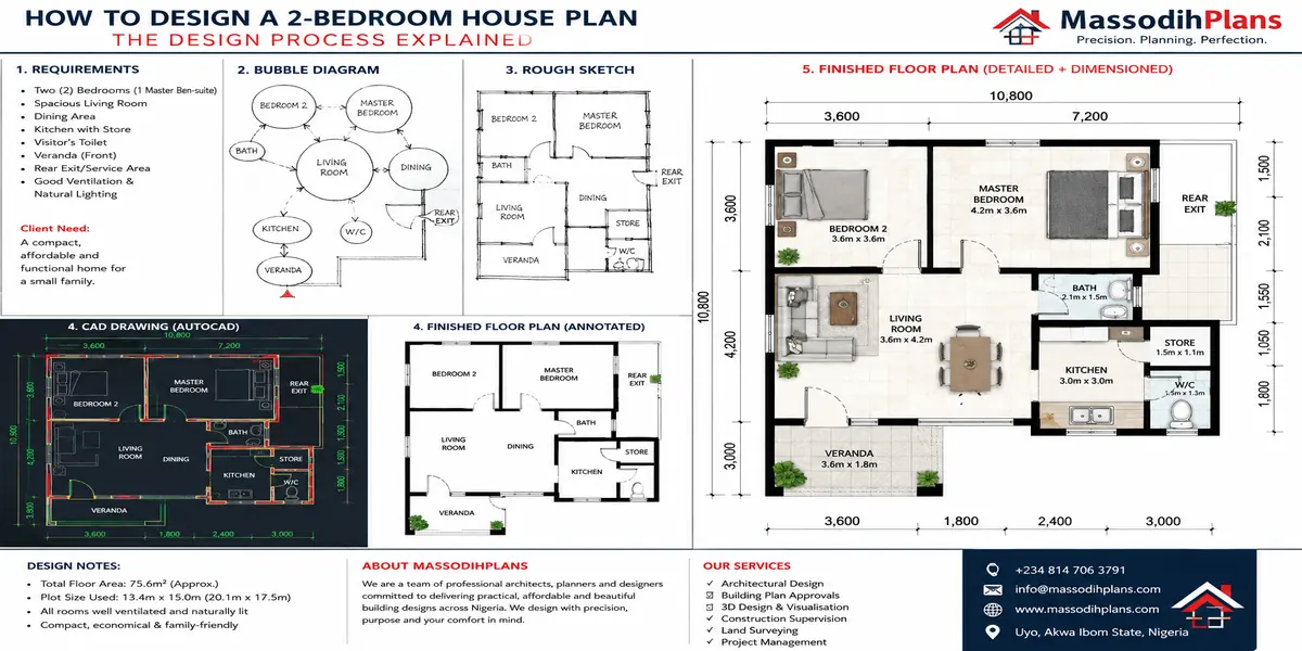
How to Design a 2 bedroom floor plans house design process
This project is a perfect example of why bedroom relationships matter just as much as bedroom sizes where you place rooms relative to each other can matter more than how big each one is.
If you’re planning a similar family-growth scenario, our article on Inspired designs for modern homes covers how to build flexibility into a small footprint from day one.
In Section below, we’ll apply this same process to a 3 bedroom house plan, currently the most requested size among our readers worldwide.
How to Design a 3-Bedroom House Plan
This is the size I design most often, so let me walk you through a real project a family of four on a 50×100 plot, wanting a proper mid-size home that would comfortably serve them for the next 15-20 years.
Requirements
They needed a master bedroom with en-suite bathroom, two additional bedrooms for their children, a shared family bathroom, a proper living room, a separate dining area, a full kitchen with pantry space, and a small home office since the wife occasionally worked from home. Parking for two cars was also essential.
Bubble Diagram
I mapped the public zone first living room, dining, and kitchen bubbles clustered near the entrance for easy guest access. Then the private zone three bedroom bubbles grouped toward the rear, with the master bedroom bubble positioned slightly separate from the two children’s bedroom bubbles for parental privacy. A small home office bubble sat near the entrance too, so work visitors wouldn’t need to pass through private family areas.
Rough Sketch
My hand-drawn layout tested this zoning in real proportions. I discovered the initial hallway connecting the three bedrooms was too long and wasted valuable floor area, so I reshaped it into an L-shaped corridor, which shortened the walking distance and freed up space for a slightly larger master bedroom.
CAD Drawing
In CAD, the design became precise: a 15×16 ft master bedroom with en-suite, two 12×12 ft children’s bedrooms sharing a 8×6 ft family bathroom, and a combined living-dining space of roughly 22×15 ft. The kitchen, at 12×10 ft, included a small adjoining pantry a detail the client specifically requested after struggling with storage in their previous home.
Finished Floor Plan
The final drawing included full dimensioning, furniture layouts showing realistic bed and wardrobe placement in each bedroom, correctly swinging doors that didn’t clash in the shortened hallway, and windows positioned for cross-ventilation in every single room something I confirmed personally using the ventilation check.
Three bedroom homes are popular for good reason they hit the sweet spot between space and cost, but only when the zoning between public and private areas is handled thoughtfully, exactly as we did here.
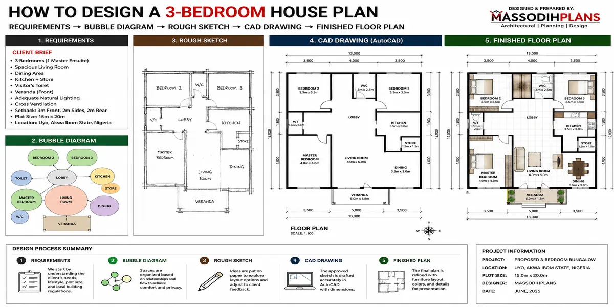
How to design 3 bedroom floor house plan
If you’re planning something similar, our article on balancing space and cost for mid-size family homes goes further into getting this size right on different plot dimensions.
In Section below, we’ll move to designing a 4 bedroom house floor plan, where space planning becomes noticeably more complex.
How to Design a 4-Bedroom House Plan
Let’s follow this same process for a larger project a family of five on a 60×100 plot, including grandparents who visited for extended periods, which made this design noticeably more complex than the 3 bedroom home.
Requirements
They needed a master bedroom with en-suite, two children’s bedrooms, a fourth bedroom designed for the visiting grandparents with easier accessibility, two additional bathrooms, a large living room, separate dining area, a big kitchen with utility space, a home office, and parking for three vehicles.
Bubble Diagram
I separated the private zone further this time the grandparents’ bedroom bubble sat on the ground floor near a bathroom, away from stairs entirely, while the master and children’s bedroom bubbles were grouped upstairs. Public zone bubbles (living, dining, kitchen) anchored the ground floor, with the home office bubble positioned near the entrance for privacy from family activity.
Rough Sketch
My hand-drawn layout tested this two-storey zoning. The first version placed the grandparents’ bathroom slightly too far from their bedroom, requiring a short hallway walk I wasn’t comfortable with given their mobility needs, so I moved the bathroom to share a direct wall with their bedroom instead.
CAD Drawing
In CAD, the ground floor took shape with the grandparents’ 13×14 ft bedroom directly beside its own 7×6 ft bathroom, a 24×16 ft combined living-dining space, and a 13×11 ft kitchen with attached utility room. Upstairs, the master bedroom measured 15×16 ft with en-suite, alongside two 12×12 ft children’s bedrooms sharing a family bathroom.
Finished Floor Plan
The completed drawing carried full dimensions, a clearly marked staircase with proper tread details as covered in Section 10, furniture layouts confirming each bedroom comfortably fit its intended furniture, and door placements designed so the grandparents’ room had a wider doorway opening for easier movement.
Four bedroom homes like this one demand more deliberate zoning than smaller houses, because you’re often designing for more than one generation’s needs at once comfort, privacy, and accessibility all have to work together, not against each other.
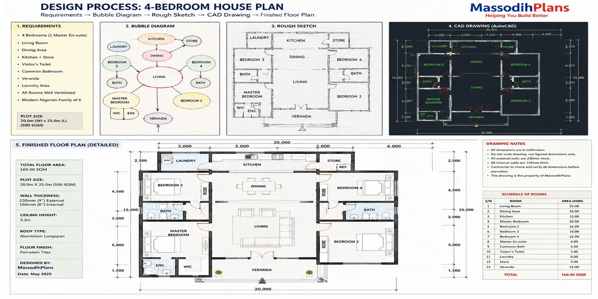
How to design 4 bedroom house plan design process
If multigenerational living is part of your own plan, our article on Best 4 bedroom house plans for small plot goes deeper into accessibility considerations like the ones we applied here.
In the next Section, we’ll teach How to Design a Self-Contained House, where we’ll also start looking closely at larger-scale circulation and zoning strategies.
How to Design a Self-Contained House
Self-contained homes are one of the most requested designs I work on, especially for clients building rental units or housing extended family with full independence. Let me break down exactly how I approach this design, piece by piece.
What Self-Contained Means
A self-contained unit is a complete, independent living space everything one household needs (sleeping, cooking, bathing, relaxing) exists within one enclosed unit, with its own entrance and no shared facilities with any other household. It’s essentially a compact, fully functional home in itself.
Bedroom
The sleeping area, whether a separate room or a defined corner in a studio-style layout. I typically allocate at least 9×10 ft even in the tightest designs, enough for a bed, small wardrobe, and clear walking space.
Living Area
A small but genuine relaxing space even 8×10 ft makes a real difference to comfort. I always resist the temptation to cut this space entirely, because a home without a proper living corner starts feeling like a hotel room, not a home.
Kitchen
A compact kitchenette with enough counter space for basic cooking, usually a single wall arrangement to save space sink, small stove area, and minimal storage, positioned near the entrance or a ventilated wall.
Bathroom
Combines toilet, shower, and basin in the smallest workable footprint, typically around 5×6 ft, positioned close to the bedroom for convenience without opening directly into the living or kitchen area.
Circulation
In such a compact space, circulation isn’t a hallway it’s the natural walking path between the four zones above. I design self-contained units so a person can move between bedroom, bathroom, kitchen, and living area without ever crossing more than a few steps.
Minimum Practical Arrangement
Through years of practice, I’ve found roughly 250-300 sq ft is the realistic minimum for a self-contained unit that doesn’t feel cramped anything smaller starts sacrificing genuine comfort, not just space.
Ventilation
Every self-contained unit needs at least two openings on different walls for cross-ventilation, even in a small footprint. I’ve corrected many single-window designs that left units stuffy and overly dependent on fans or air conditioning.
Privacy
Since these units often sit close to a main house or share a compound, window placement matters enormously. I angle or position windows to avoid direct sightlines into neighboring units or the main house.
Door Placement
The main entrance should open independently, never through another household’s space. Internal doors (bathroom, if separated) should swing without blocking movement in such a tight footprint.
Window Placement
Beyond ventilation, windows should capture natural light without compromising privacy I favor slightly higher window positions in bathroom and bedroom areas for exactly this reason.
Furniture Arrangement
I always sketch real furniture into these small layouts early, because self-contained units have zero tolerance for wasted space. A bed placed wrong can block a window; a wardrobe placed wrong can block a door swing.
Plumbing Efficiency
I always group the kitchen and bathroom close together, sharing plumbing lines where possible. This single decision reduces construction cost significantly and simplifies future maintenance a detail many first-time builders overlook until the bills arrive.
Self-contained design is really an exercise in discipline every decision has less room for error than in a larger home.
For more on designing efficiently within tight limits, our article on What are the best nigerian house plans for small plot property investment without losing comfort expands on several principles used here. Learn how to design How to Design a Duplex below:
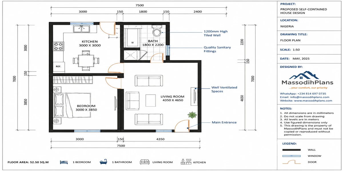
How to Design a Self-Contained House
How to Design a Duplex
Duplexes are a design I return to often, especially for clients wanting rental income, extended family arrangements, or simply making the most of a good plot. Let me walk through the real considerations, floor by floor.
Ground Floor
The ground floor typically carries the public and service functions living room, dining area, kitchen, and often a guest bedroom or powder room for visitors who shouldn’t need to climb stairs. I usually place the main entrance and staircase here in a position that’s easy to find but doesn’t dominate the living space.
Upper Floor
This is where private, quieter spaces belong bedrooms, family bathrooms, and sometimes a small family lounge separate from the main downstairs living area. Keeping bedrooms upstairs naturally separates public activity from private rest, which clients consistently tell me makes daily life feel calmer.
Staircase
The staircase is often the most underrated element in duplex design. I always position it centrally enough to serve both floors efficiently, with proper tread depth and riser height for comfort and safety remember from Section 10, poorly designed stairs are one of the most common on-site hazards I’ve had to correct.
Vertical Circulation
Beyond the staircase itself, vertical circulation means how people and even furniture move between floors. I always check: can a mattress or sofa actually get up that staircase during move-in? I’ve seen beautiful designs fail this simple practical test.
Bedroom Arrangement
For a two-unit duplex (stacked, one unit per floor), each floor needs its own complete bedroom arrangement. For a single-family duplex spanning both floors, I group bedrooms upstairs together, master bedroom often positioned furthest from the staircase for maximum quiet.
Living Spaces
In a single-family duplex, one generous living area downstairs usually works better than splitting living space across both floors. In a two-unit rental duplex, each unit needs its own independent living area never shared.
Guest Areas
A guest bedroom or restroom on the ground floor is a detail I recommend strongly, especially for elderly visitors who shouldn’t need to climb stairs. It’s a small addition that makes a real difference in daily hospitality.
Service Areas
Kitchen, utility, and storage areas belong on the ground floor for single-family duplexes, positioned near the rear or side for easy access to deliveries, waste disposal, and outdoor drying areas if needed.
Plumbing Stacking
This is one of the most important, least visible design decisions in any duplex. I always align bathrooms and kitchens vertically between floors wherever possible stacking plumbing lines directly above each other drastically reduces pipe runs, construction cost, and future maintenance headaches.
Structural Considerations
A duplex carries more structural weight than a single-storey home, so beam sizing, column placement, and foundation depth all need careful engineering calculation. I never finalize a duplex floor plan without structural engineer input, because a beautiful upstairs layout means nothing if it’s not properly supported underneath.
Roof Arrangement
The roof needs to account for the full building height and often a more complex shape than a bungalow roof, especially where the design includes varying roof lines over different sections. Proper drainage planning matters even more here, since water has a longer path to travel off a taller structure.
Designing a duplex is really an exercise in coordination every decision on the ground floor has direct consequences upstairs, from where pipes run to where structural columns must sit. Get that coordination right from the start, and a duplex gives you excellent value from your land two full living arrangements, or one spacious family home, built smartly rather than simply built big. Let me show you How to Design a Small House in the next section. Also see our Duplex House Plans guide
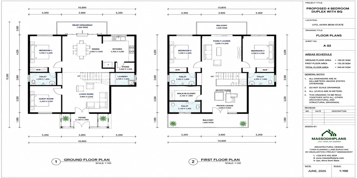
How to Design a Duplex
How to Design a Small House
Small houses are where good design matters most, because there’s zero room to hide a bad decision. In my years of practice, some of my proudest work has actually been on small homes proving that “small” and “cramped” are two completely different things when the design is done right.
Space-Saving Techniques
Every decision in a small house should ask one question: does this earn its space? I favor sliding doors over swinging ones where possible, since a swinging door needs clear floor space just to open. I also avoid unnecessary internal walls fewer walls mean more usable floor area and lower construction cost.
Open-Plan Layouts
Combining living, dining, and sometimes kitchen into one continuous space is one of the most effective tricks in small home design. It removes wasted wall space between rooms and makes the entire home feel noticeably larger than its actual square footage.
Multi-Purpose Rooms
A home office corner that doubles as a guest sleeping nook, or a dining table that also serves as a workspace I design these dual-use spaces constantly for clients on tight plots. The key is choosing furniture and layouts that transition easily between functions.
Built-In Storage
Freestanding wardrobes and cabinets eat valuable floor space. I push clients toward built-in storage instead under-stair cabinets, wall-recessed shelving, and closets designed into the wall thickness itself wherever structurally possible. It’s storage that doesn’t cost you floor area.
Efficient Circulation
In a small house, every hallway is space stolen from a room. I design circulation paths as short and direct as possible, sometimes eliminating hallways entirely by letting rooms open directly into each other in a logical sequence.
Compact Kitchens
A single-wall or galley-style kitchen layout works beautifully in small homes, keeping everything within easy reach without demanding excess floor area. I always prioritize counter space near the stove and sink over a large, open kitchen island that a small home simply can’t afford.
Compact Bathrooms
A well-planned 5×7 ft bathroom can feel perfectly comfortable with the right fixture placement toilet and shower positioned to avoid wasted corner space, and a corner sink if floor area is especially tight.
Reduced Corridors
Beyond general circulation, I specifically look for corridors that serve only one purpose and eliminate them wherever a room can connect directly to another instead. Every foot of corridor removed is a foot added back to a living space.
Natural Lighting
Small homes benefit enormously from generous natural light, since it makes limited square footage feel more open. I favor larger windows relative to wall size in small designs, along with strategically placed skylights in windowless interior areas like bathrooms or hallways.
Cross Ventilation
As we covered in earlier sections, windows on opposite or adjacent walls allow air to move naturally through the home. In small houses, this becomes even more important, since there’s less air volume to begin with good airflow keeps a compact home feeling fresh rather than stuffy.
Here’s what I’ve learned designing small homes for clients across different countries and climates: the families who end up happiest aren’t the ones who got the biggest house they could afford they’re the ones who got the smartest layout for the space they actually had. A well-designed 800 sq ft home will always outperform a poorly designed 1,500 sq ft one, every single time. Small House Design guide
How to Design a House for a Small Plot
Small plots are becoming more common everywhere, especially in cities across the US, UK, Canada, Nigeria, and beyond, as land prices rise and available plots shrink. This is a challenge I face constantly in my practice, and honestly, some of my most creative work has come from small, difficult plots. Let me show you how I approach it.
Setbacks
Before designing anything, I confirm the exact setback requirements from local authorities the mandatory distance between your building and each plot boundary. On a small plot, setbacks can easily consume 30-40% of your usable land, so this number shapes everything that follows.
Plot Coverage
This refers to the percentage of your plot the building footprint is legally allowed to occupy. Many jurisdictions cap this around 50-60% for residential plots. Knowing this figure early prevents designing a footprint that later gets rejected at approval stage.
Building Orientation
On a small plot, orientation becomes critical rather than optional. I study sun path and prevailing wind direction carefully, positioning living areas to catch morning light and bedrooms away from harsh afternoon heat, since there’s little room to compensate with large setbacks or landscaping buffers.
Parking
Parking on a small plot demands creative thinking sometimes a single covered space instead of an open driveway, or parking positioned under an overhanging upper floor to avoid wasting ground-level footprint that could otherwise be living space.
Light Wells
When a plot is too tight for generous windows on every wall, I introduce light wells small vertical shafts that bring daylight and ventilation down into the center of a home, especially useful for interior bathrooms or hallways that would otherwise have no natural light at all.
Courtyards
Even a compact 6×6 ft internal courtyard can transform a small home, pulling light and air into the center of the building while preserving privacy from the street and neighbors. I’ve used this trick often on plots too narrow for generous side windows.
Side Setbacks
These are usually the tightest constraint on a small plot. I work closely with the minimum legal side setback, sometimes just a few feet, which limits window placement on those walls and pushes me to rely more on front, rear, or internal light sources instead.
Rear Setbacks
The back of a small plot often becomes valuable outdoor space even a modest paved area or small garden here adds genuine quality of life, so I resist the urge to build right up to the rear boundary even when technically permitted.
Narrow Frontage
A narrow-fronted plot pushes the design deeper into the land rather than wide across it. I typically arrange rooms in a linear sequence from front to back, using light wells or a mid-house courtyard to keep the deeper interior rooms from feeling dark.
Vertical Development
When your footprint is limited, building upward is usually the smartest answer. A 2 or 3-storey design on a small plot can deliver the same room count as a single-storey home on a much larger plot, without sacrificing comfort.
Privacy
Small plots often sit close to neighboring buildings, so privacy needs deliberate handling higher window placement, angled openings, or strategic wall positioning to avoid direct sightlines into neighboring properties or from the street.
Drainage
With less open ground to absorb rainwater, drainage planning becomes more important, not less. I always ensure roof and surface water has a clear, engineered path off the property, especially where plot coverage is high and open soil is limited.
Access
Finally, confirm there’s adequate access for construction vehicles, deliveries, and daily use narrow plots sometimes have tight access lanes that limit what materials or equipment can realistically reach the site.
Designing for a small plot isn’t about compromise it’s about precision. Every decision matters more because there’s less room for error, and that’s exactly what makes a well-designed small-plot home so satisfying to deliver. Our Small-Plot House Plans collection
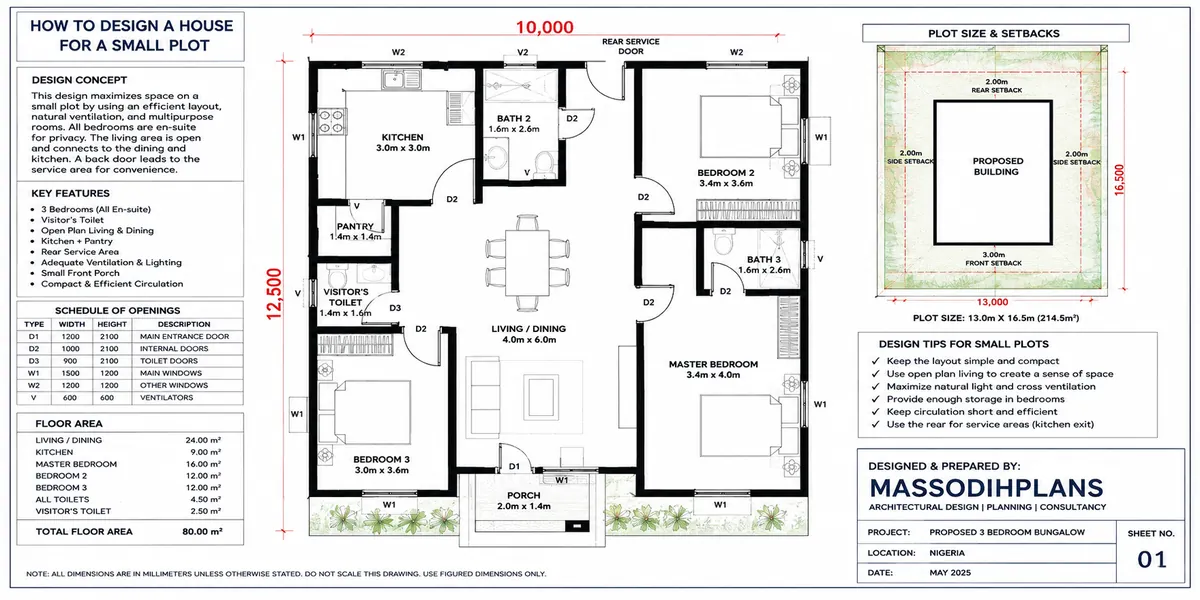
How to Design a House for a Small Plot
How to Draw a House Plan in AutoCAD
Once your design is finalized on paper, the next step is turning it into an accurate, professional drawing using AutoCAD. Let me walk you through the actual process, step by step, the way I do it with every project.
1. Setting Units
Before drawing anything, set your drawing units correctly. Type “UNITS” in the command line and choose your preferred format feet and inches, or millimeters/meters, depending on your project’s standard. Getting this right at the start prevents scaling errors later that are painful to fix.
2. Drawing Walls
Use the “LINE” or “PLINE” (polyline) command to draw your wall outlines based on your floor plan dimensions. I typically draw walls as a closed polyline outline first, establishing the overall building footprint before adding internal partitions.
3. Wall Thickness
Use “OFFSET” to create the second line of each wall, giving it real thickness typically 9 inches (230mm) for exterior walls and 4-6 inches (100-150mm) for interior partitions, though this varies by construction method and local standards.
4. Doors
Draw doors using a simple rectangle for the door leaf and an arc (using the “ARC” command) to show the swing path. Many designers build a reusable door block once, then insert it wherever needed using “INSERT,” saving significant time across a project.
5. Windows
Represent windows as a break in the wall line, typically shown with two or three parallel lines within the opening using “OFFSET” and “TRIM.” Like doors, creating a window block you can reuse across the drawing speeds up your workflow considerably.
6. Dimensions
Use the “DIMLINEAR,” “DIMALIGNED,” and “DIMCONTINUE” commands to add accurate measurements to every wall, room, and opening. Always double-check your dimension style settings match your chosen units before adding dimensions across the whole drawing.
7. Furniture
Insert furniture blocks beds, sofas, tables, kitchen counters either from AutoCAD’s built-in block libraries or imported custom blocks. This step helps verify that rooms are genuinely functional once furnished, not just correctly sized on paper.
8. Stairs
Draw stairs using the “LINE” or “RECTANGLE” command repeated for each step (tread), combined with an arrow (using “PLINE” with an arrowhead) showing the direction of travel, up or down. Confirm your tread depth and riser height match comfortable, code-compliant standards before finalizing.
9. Hatching
Use the “HATCH” command to fill wall sections, indicating material type concrete, brick, insulation using standard hatch patterns. Consistent hatching across a drawing set makes it far easier for contractors to read material types at a glance.
10. Text
Add room labels, notes, and specifications using the “TEXT” or “MTEXT” command. Keep font size and style consistent throughout the drawing I recommend setting a text style early and sticking to it across every sheet.
11. Layers
Organize your drawing using “LAYER” separate layers for walls, doors, windows, dimensions, furniture, and text, each with its own color and lineweight. Proper layering makes it easy to isolate, edit, or hide specific elements without disturbing the rest of the drawing.
12. Lineweights
Assign appropriate lineweights to each layer thicker lines for walls and structural elements, thinner lines for furniture and hatching, medium weight for dimensions. This visual hierarchy makes the finished drawing much easier to read at a glance.
13. Annotation
Beyond basic text, annotation includes section markers, elevation indicators, and general notes referencing construction standards or special instructions. Use AutoCAD’s annotation scaling feature so text and symbols stay properly sized across different viewport scales.
14. Layout
Switch to “Layout” tabs (Paper Space) to arrange your drawing for printing set up viewports showing your model at the correct scale, add a title block with project information, and organize multiple sheets if your project includes several drawings.
15. Printing
Use “PLOT” to print your drawing, carefully selecting the correct paper size, scale, and plot style table (often “monochrome.ctb” for clean black-and-white construction drawings). Always preview before committing to a final print to catch layout issues early.
16. PDF Export
For digital sharing, export your layout as a PDF using “PLOT” and selecting “DWG to PDF” as your plotter, or use “EXPORTPDF” for a quicker method. A properly exported PDF preserves your lineweights and scale, making it ready to send directly to clients, contractors, or approval authorities.
A Final Practical Note
Drawing in AutoCAD is a skill that improves significantly with repetition your first few plans will take considerably longer than plans number twenty or thirty, once your block library and layer standards are properly set up. I recommend building a personal template file with your preferred units, layers, text styles, and common blocks already configured, so every new project starts from a solid, consistent foundation rather than from scratch.
Mastering this workflow is what separates a rough sketch from a genuinely construction-ready drawing the kind any builder, engineer, or approval authority can pick up and execute with confidence. Our AutoCAD House Plan Tutorial
How to Draw Elevations
Once your floor plan is complete, the next step is showing how the house actually looks from outside. This is where elevations come in, and it’s a process I walk through with every project after the floor plan is locked down.
What an Elevation Is
An elevation is a straight-on, flat view of one side of your building no perspective, no distortion, just an accurate, to-scale representation of that wall as seen from directly outside it. Think of it as a “photograph” taken from infinitely far away, removing any perspective distortion.
Front Elevation
Shows the main facade usually the most detailed and important elevation, since it’s the first impression of the home. This is the view most homeowners get excited to see first.
Rear Elevation
Shows the back of the house, often revealing service areas, kitchen windows, or rear extensions that don’t feature in the front view.
Side Elevations
Left and right elevations show the narrower sides of the building, revealing roof slopes, side windows, and how the house sits relative to its neighbors or side setbacks.
Ground Line
A horizontal reference line representing the natural ground level, from which all vertical heights on the elevation are measured. Getting this line accurate matters enormously on sloped plots.
Floor Levels
Horizontal lines marking each floor’s height relative to the ground line ground floor, first floor, and so on, pulled directly from your building sections to keep everything consistent.
Roof Line
Shows the roof’s shape, pitch, and highest point as seen from that particular side. This must align precisely with your roof plan from Section 2, since inconsistency here causes real construction confusion.
Windows
Drawn to scale in their exact wall positions, matching the floor plan precisely same size, same location, just now shown vertically instead of from above.
Doors
Same principle as windows drawn accurately in their real position and height, matched exactly to the floor plan below.
Materials
Elevations indicate exterior materials brick, render, wood cladding, stone often using texture symbols or hatching, and sometimes color rendering for presentation purposes.
Finishes
Beyond raw materials, finishes cover paint colors, surface textures, and trim details the layer that gives a house its final visual character.
Dimensions
Vertical dimensions showing floor-to-floor heights, window heights, and overall building height are added to guide construction accurately.
Annotation
Notes clarifying material specifications, finish types, or construction details that aren’t obvious from the drawing alone, keeping the elevation fully informative for builders.
From Floor Plan to Elevation: The Real Process
Here’s how I actually move from a finished floor plan to a complete elevation. I start by “projecting” straight up from the floor plan’s outer wall line every door and window position on that wall gets carried upward as a vertical guideline. Using the building section (covered in Section 2) for accurate floor-to-floor heights, I mark the ground line, then each floor level above it.
Next, I draw the wall outline itself between these height guidelines, followed by placing each door and window at its correct height and width, using the vertical guidelines from the floor plan to keep horizontal position accurate. The roof line gets added last, matching the pitch and shape from the roof plan.
Once the basic outline is complete, I add material hatching, texture, and finish notes, then finish with dimensions and annotations. The result is a drawing that isn’t just visually pleasing it’s a precise, buildable translation of the exact same house shown in the floor plan, just viewed from the outside. Understanding house plan elevation drawings.
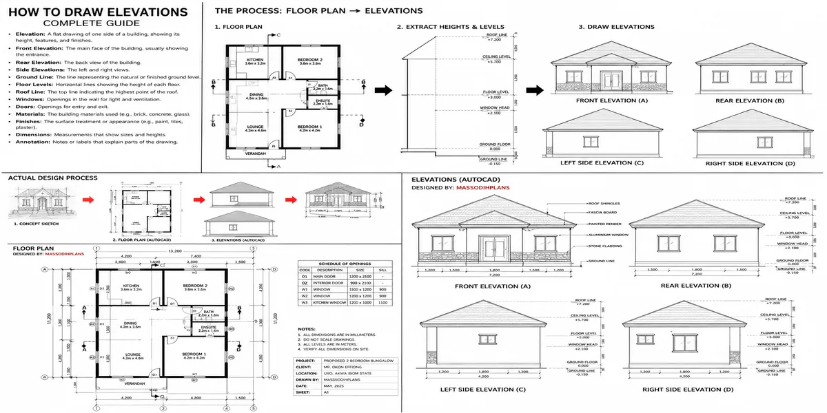
How to draw building elevations
This direct link between floor plan and elevation is exactly why the two drawings must always match perfectly any mismatch between them is one of the fastest ways to create confusion and costly errors on-site.
How to Draw Building Sections
After the floor plan and elevations, building sections complete the picture by showing what’s happening vertically inside the house the part no elevation or floor plan alone can reveal.
What a Section Is
A section is a “sliced” view of the building, as if you cut straight through it with a giant knife and looked directly at the exposed interior floor levels, wall heights, roof structure, all in one clear vertical view.
Section Line
This is the reference line drawn on the floor plan (introduced back in Section 10) showing exactly where that imaginary cut passes through the building, labeled with letters like “A-A” so anyone can trace which section corresponds to which cut.
Cutting Plane
The cutting plane is the actual imaginary vertical surface along that section line everything the plane passes through gets shown in full detail, while everything beyond it is shown only in outline or omitted entirely.
Foundation
The section reveals foundation depth, footing width, and how the structure connects to the ground below details completely invisible in a floor plan or elevation.
Ground Floor
Shows the ground floor’s construction slab thickness, damp-proofing layers, and floor finish, all stacked in their real vertical relationship.
Floor Slab
For multi-storey buildings, each floor slab’s thickness and structural makeup is shown clearly, along with how it connects to supporting walls or beams.
Wall
The full height of the wall is revealed, showing its construction layers blockwork, plaster, insulation if used from floor to ceiling, all in accurate proportion.
Ceiling
Shows ceiling height and construction, including any drop-ceiling design or exposed beam detail that wouldn’t be obvious from a floor plan alone.
Roof
Reveals the actual roof structure rafters, trusses, pitch angle, and how it connects to the top of the walls, all details essential for the roofing contractor.
Staircase
One of the most valuable things a section shows the real, accurate rise and run of every step, along with headroom clearance, which is nearly impossible to judge from a floor plan alone.
Levels
Every floor and reference height gets marked clearly, tying the section back to the same level markers used in your elevations, keeping the entire drawing set consistent.
Dimensions
Vertical dimensions throughout floor-to-ceiling height, foundation depth, roof height give the builder precise, non-negotiable numbers to construct from.
Structural Elements
Beams, columns, and reinforcement details often appear clearly for the first time in a section, since this is genuinely the only drawing type that reveals what’s happening inside the walls and floors themselves.
Demonstrating the Process
Here’s how I actually build a section from scratch. I start with the section line already marked on the finished floor plan say, cutting straight through the living room, hallway, and a bedroom. I draw a horizontal ground line first, then mark each floor level above it using the same heights confirmed in the elevation drawings, so everything stays consistent across the full drawing set.
Next, I draw the foundation and ground floor slab at the base, then build the walls upward to their correct height, marking window and door openings exactly where that section line passes through them on the floor plan. If the staircase falls within the cutting plane, I draw each step with its real rise and run, checking headroom clearance carefully as it passes beneath the floor above.
Finally, I add the roof structure at the top, matching the pitch from the roof plan and elevations, then complete the drawing with dimensions, level markers, and any structural elements the section reveals. Drawing Building Sections, reading a full house plan set.
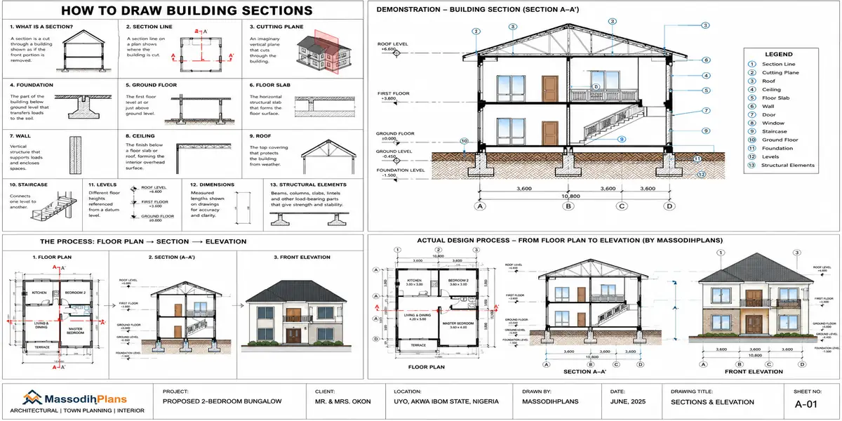
How to draw house building plans sections
A well-drawn section is often the drawing that catches problems no other drawing can a beam that doesn’t quite clear a doorway, a staircase with insufficient headroom, a roof pitch that doesn’t match the walls below it. This is exactly why I never skip this step, no matter how simple a project seems on the surface.
How to Design a Roof Plan
The roof is often the last thing people think about, yet it’s one of the most important drawings in the entire set get it wrong, and you’ll be dealing with leaks for years. Let me walk you through it the way I approach every roof design.
Roof Types
Choosing a roof type isn’t just about looks it depends heavily on climate, budget, and the shape of the building beneath it. Let’s go through the common options.
Gable
A simple, triangular roof shape with two sloping sides meeting at a ridge, forming a triangle at each end wall. It’s affordable, easy to construct, and sheds rain and snow effectively one of the most common roof types I design worldwide.
Hip
All four sides slope downward toward the walls, with no vertical triangular ends. Hip roofs handle strong winds better than gables, which is why I recommend them often in coastal or high-wind areas.
Mansard
A four-sided roof with two slopes on each side a steep lower slope and a shallower upper slope, often creating extra usable attic space. Popular in more formal, classic architectural styles.
Flat Roof
Not perfectly flat in practice it carries a very slight slope for drainage, usually under 10 degrees. Common in modern and contemporary designs, but demands excellent waterproofing since water has less natural help draining off.
Mono-Pitch
A single sloping surface, sometimes called a skillion roof. Simple to construct and popular in modern minimalist designs, especially for smaller structures or extensions.
Roof Pitch
This is the steepness of the roof, usually expressed as a ratio or angle. Steeper pitches shed rain and snow faster, which matters enormously in heavy-rainfall or snowy climates, while shallower pitches suit drier regions and modern aesthetics.
Ridge
The horizontal line at the very top where two roof slopes meet. It’s the highest point of the roof and a critical reference line when drawing both the roof plan and elevations.
Hip (as a Roof Feature)
Beyond the roof type named “hip,” a hip is also the term for the sloped edge where two roof planes meet at an external corner it runs diagonally from the ridge down to the eave.
Valley
The opposite of a hip an internal angle where two roof slopes meet, creating a channel that directs rainwater downward. Valleys need careful waterproofing detail, since they carry the heaviest concentrated water flow on the entire roof.
Eaves
The edge of the roof that overhangs the building’s walls. Eaves protect walls from rain and provide shade, and I always size them generously in hot or wet climates for genuine practical benefit, not just appearance.
Fascia
The horizontal board fixed along the roof’s edge, right where the roof meets the outer wall. It supports the lower edge of the roof covering and provides the mounting point for gutters.
Gutters
Channels running along the roof edge, usually attached to the fascia, that collect rainwater running off the roof surface and direct it toward downpipes rather than letting it fall straight down the walls.
Downpipes
Vertical pipes connected to the gutters, carrying collected rainwater down to ground level and away from the building’s foundation a detail I take very seriously, since poor downpipe placement is a common cause of foundation dampness.
Roof Drainage
Beyond gutters and downpipes, overall roof drainage means the complete water journey from roof surface, through valleys, into gutters, down through downpipes, and finally away from the building via proper ground drainage, exactly as discussed in Section 6’s plot drainage considerations.
Bringing It Together
When I design a roof plan, I always start with the building’s shape and climate first, then choose the roof type that genuinely suits both not simply what looks fashionable. From there, I mark the ridge, hips, and valleys accurately based on the chosen roof type, set an appropriate pitch, and finally plan eaves, gutters, and downpipes to manage water responsibly around the entire building. Designing a Roof Plan, roofing materials by climate zone.
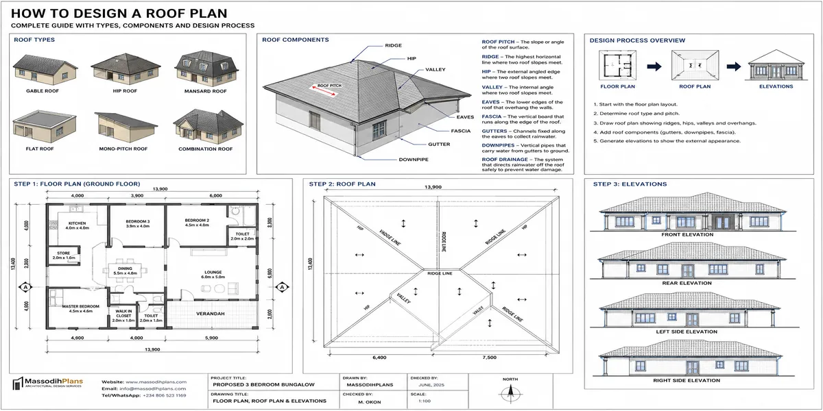
How to design a roof plans
A well-designed roof plan protects everything beneath it. I’ve corrected more water-damage complaints caused by poor roof drainage than almost any other construction issue which is exactly why this drawing deserves just as much careful attention as your floor plan.
How to Draw Electrical Plans
Electrical plans are one of the drawings clients underestimate most, right up until construction starts and someone asks “where exactly should this switch go?” Let me practically explain to you how I approach it properly.
Lighting Points
I mark every ceiling light, wall light, and decorative fixture position on the plan, drawn directly onto the floor plan at its exact intended location. I always think about how each room will actually be used a kitchen needs brighter, more evenly spread lighting than a bedroom, for example.
Switches
Switches are placed near doorways, at a comfortable, consistent height, positioned so a person naturally reaches for them upon entering a room. For rooms with two entrances, I add two-way switching so you can turn a light on or off from either door.
Socket Outlets
I plan sockets around real furniture layout, not guesswork near desks, beside beds, behind where a TV or fridge will sit. A good rule I follow: never make a client stretch an extension cord across a room because a socket was placed without thinking about actual use.
Distribution Board
This is the central point where electricity from the main supply splits into individual circuits for different parts of the house. I position it somewhere accessible but out of the way — often near the entrance, utility area, or garage never hidden behind furniture or in a hard-to-reach spot.
Dedicated Circuits
Certain high-power appliances need their own individual circuit, rather than sharing with general sockets this prevents overload and improves safety. I always plan these separately and clearly label them on the electrical plan.
AC Points
Air conditioning units need dedicated circuits and carefully planned outlet positions, usually near the ceiling or a specific wall height depending on the unit type. I confirm AC unit locations early, since retrofitting one after walls are finished is disruptive and costly.
Water Heater Points
Water heaters, especially instant or high-capacity units, draw significant power and need their own dedicated circuit, positioned close to the bathroom or kitchen they serve to minimize pipe and wire runs.
Kitchen Appliances
Kitchens need multiple dedicated circuits one for major appliances like an oven or standalone cooker, separate circuits for smaller counter appliances, and enough general sockets for daily use without overloading a single line.
Exterior Lighting
Outdoor lighting for entrances, pathways, and security needs its own weatherproof fixtures and switching, often controlled separately from interior lighting, sometimes with a timer or sensor depending on the client’s preference.
Symbols
Every electrical element uses a standard symbol circles for lights, specific icons for switches, sockets, and appliance points kept consistent throughout the drawing so any electrician can read the plan without confusion.
Circuit Routes
Beyond just marking points, I trace the actual wiring path connecting each switch to its light and each socket back toward the distribution board, usually shown as dashed lines, giving the electrician a clear installation roadmap.
Electrical Legends
Every electrical plan needs a legend a small reference key explaining what each symbol means, since symbols can vary slightly between designers and regions. I include this on every single electrical drawing without exception, because assuming an electrician will “just know” a symbol is how mistakes happen on-site.
Electrical planning done properly means the client never has to run an extension cord, never has an outlet blocked by furniture, and never wonders why a switch is inconveniently placed. It’s a small drawing with an enormous daily impact on how comfortable a home actually feels to live in. See Electrical Layout Guide.
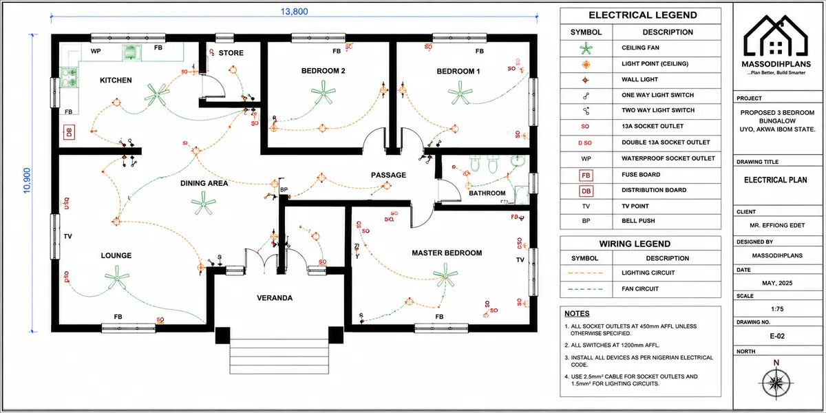
How to Draw Electrical Plans
How to Draw Plumbing Plans
Plumbing is one of those systems nobody thinks about until it goes wrong a burst pipe or a blocked drain can turn a beautiful home into a genuine headache. Let me show you how I approach plumbing plans properly, so problems like these never happen in the first place.
Cold-Water Supply
This is the network of pipes bringing fresh water from the main source municipal supply, borehole, or storage tank to every fixture that needs it. I always plan the shortest, most direct routes possible, since longer pipe runs mean more pressure loss and higher material cost.
Hot-Water Supply
A separate network of pipes carrying heated water from your water heater to relevant fixtures showers, basins, kitchen sinks. I position water heaters as close as practically possible to the fixtures they serve, minimizing heat loss and the frustrating wait for hot water to arrive.
Soil Pipes
These carry waste specifically from toilets to the main drainage or septic system. Soil pipes need a consistent downward slope to keep waste flowing properly by gravity getting this slope wrong is one of the most common plumbing mistakes I’ve had to correct on-site.
Waste Pipes
Separate from soil pipes, these carry wastewater from sinks, showers, and basins generally called “grey water.” I plan these routes to connect efficiently into the main drainage system, ideally sharing routes with soil pipes where the layout allows.
Vent Pipes
Often overlooked, vent pipes allow air into the drainage system, preventing suction that would otherwise pull water out of trap seals and let sewer gas smells into the house. Every plumbing system needs proper venting skipping this is a mistake that shows up as bad odors months after move-in.
Toilets
I position toilets on plumbing plans matched exactly to their floor plan location, connected directly to the soil pipe with the shortest, most direct route possible, since long horizontal runs increase blockage risk.
Showers
Shower drainage needs proper floor slope toward the drain point, along with waterproofing detail at the connection. I always coordinate this with the floor finish plan to avoid water pooling issues after construction.
Wash Basins
Connected to both hot and cold water supply lines and a waste pipe, positioned according to the bathroom layout. I keep basin plumbing close to the main wet wall wherever possible, reducing pipe runs and cost.
Kitchen Sinks
Similar principle to wash basins, but kitchen sinks often need a slightly larger waste pipe to handle food particles and grease, plus sometimes a separate grease trap depending on local regulations.
Floor Drains
Placed in bathrooms, laundry areas, and sometimes garages, floor drains handle general water runoff and accidental overflow. I make sure the floor always slopes gently toward these drains, never away from them.
Septic System
For homes without municipal sewage connection, a septic system treats wastewater on-site through a tank that separates solids from liquids. I always calculate tank size based on household occupancy and coordinate its position with local regulations regarding distance from the house and water sources.
Soakaway
Connected to the septic system, a soakaway allows treated liquid waste to filter safely into the surrounding soil. Positioning matters enormously here too close to a water source or foundation risks contamination or structural damage.
Inspection Chambers
These are access points built into the underground drainage system, allowing maintenance access to clear blockages without digging up the entire pipe run. I space these strategically along drainage routes, especially at points where pipes change direction, since that’s exactly where blockages tend to form.
Bringing It All Together
A good plumbing plan traces every drop of water’s complete journey from supply source to final disposal with every pipe sized, sloped, and routed correctly. I always coordinate this drawing closely with the electrical plan too, since both systems often share wall cavities and need to avoid clashing during installation.
Get plumbing right at the drawing stage, and you’ll likely never think about it again for decades. Get it wrong, and you’ll be opening up finished walls and floors to fix problems that proper planning could have prevented entirely which is exactly why I treat this drawing with the same seriousness as the structural plan itself. Drawing Plumbing Plans Layout Guide.
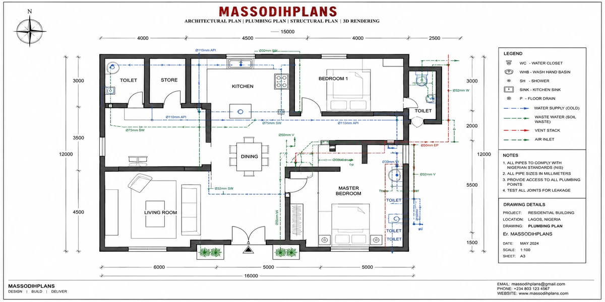
How to Draw Plumbing Plans
How to Design the Foundation Plan
The foundation plan is where architectural design meets structural engineering directly, and it’s important I’m honest with you about where my role as an architectural designer ends and where a structural engineer’s role must begin. Let me walk you through both sides clearly.
Foundation Types
The right foundation type depends on soil conditions, building load, and local climate this is never a decision made from architectural preference alone.
Strip Foundation
A continuous strip of concrete running beneath load-bearing walls, common in most standard residential buildings on reasonably stable soil. It’s straightforward, cost-effective, and suits the vast majority of small to medium homes.
Pad Foundation
Individual concrete pads supporting isolated points of load, typically beneath columns rather than continuous walls. Common in framed structures where the building’s weight transfers through specific column points rather than along wall lines.
Raft Foundation
A single, continuous concrete slab supporting the entire building footprint at once, spreading the load evenly across the whole area. Often used on weaker or less predictable soil, where individual strips or pads risk uneven settlement.
Ground Beams
Horizontal concrete beams connecting foundation points together whether pads or piles tying the structure into one stable unit and helping distribute load evenly across the foundation system.
Footings
The widened base at the bottom of a foundation wall or column, spreading the building’s weight over a larger soil area to reduce pressure per square inch and prevent excessive settling.
Foundation Walls
The walls rising from the footing up to ground floor level, forming the base that the rest of the house sits on. These need to be built with proper waterproofing, since they sit partially below ground and face constant soil moisture.
Columns
Vertical structural elements transferring load from upper floors straight down to the foundation. Their exact position must align precisely between the structural drawings and the architectural floor plan above any mismatch causes serious construction problems.
Setting Out
This is the process of accurately transferring the foundation plan’s measurements onto the actual physical site marking exact positions with pegs and string lines before any digging begins. Precise setting out is what ensures the finished building matches the drawing exactly.
Relationship Between Foundation and Floor Plan
The foundation plan must align perfectly with the floor plan above it every load-bearing wall and column position on the foundation plan needs to correspond exactly to the walls and columns shown in the floor plan. I always cross-check both drawings side by side before finalizing either one, because even a small misalignment here creates real structural problems once construction begins.
An Important Distinction: Architectural Planning vs Structural Engineering
Here’s something I always make completely clear to my students and clients, and I want to be equally clear with you here. As an architectural designer and town planner, my role is to determine the layout, positioning, and general arrangement of the foundation where walls and columns sit, how the foundation plan relates to the floor plan above, and how the overall design fits the site.
However, the actual structural calculations foundation depth, footing dimensions, concrete strength, reinforcement quantities, and confirmation that a chosen foundation type can safely support the building’s real load on that specific soil must always come from a qualified structural engineer, ideally supported by a proper soil test report. I never finalize a foundation plan without structural engineering sign-off, and I strongly encourage every homeowner reading this to insist on the same for their own project.
Skipping this step to save money at the planning stage is, without exception, one of the most expensive mistakes I’ve seen in this industry because problems in a foundation are the hardest and costliest to fix once concrete has already been poured. Foundation types explained
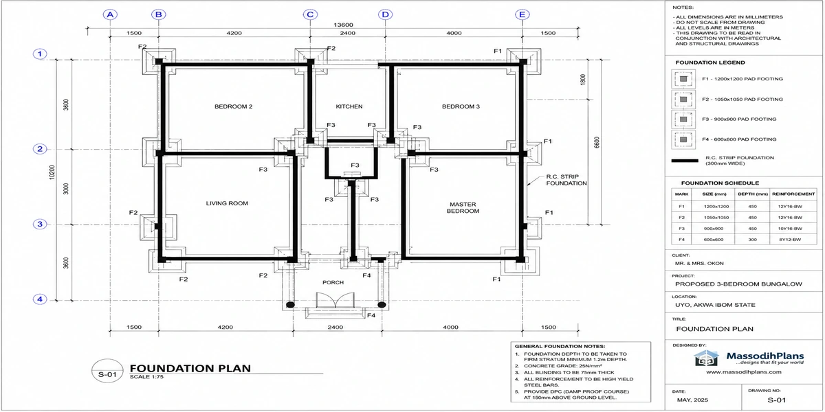
How to Design the Foundation Plan
How to Design a Site Plan
The site plan is often the very first drawing any approval authority looks at, because it shows how your house sits within the larger context of the land, roads, and surrounding features. Let me walk you through how I build one properly.
Plot Boundary
This is the legal edge of your land, drawn accurately from your survey document, usually with exact dimensions and bearing angles for each boundary line. Every other element on the site plan is positioned relative to this boundary.
Building Footprint
The outline of your house as it sits on the plot, positioned according to confirmed setbacks. I always double-check this footprint matches the ground floor plan exactly any mismatch here creates confusion at approval and construction stages.
Setbacks
As covered in earlier sections, setbacks are the required distances between your building and each boundary line. I mark these clearly on the site plan with dimension lines, since approval authorities check these figures very closely.
Road
The site plan shows the road or street the plot fronts, including road width where relevant, since this affects access planning, drainage direction, and sometimes setback requirements too.
Driveway
The path from the road into the property, sized appropriately for vehicle access and positioned to avoid awkward turning angles. I plan driveways early, since retrofitting one after landscaping or boundary walls are built is far more difficult.
Parking
Dedicated parking areas or garage positions are marked clearly, sized according to how many vehicles the household needs, as we discussed back in Section 9.
Landscaping
Gardens, lawns, trees, and paved outdoor areas are shown on the site plan, giving a complete picture of how the outdoor space will be used, not just the building itself.
Drainage
The site plan shows how surface water and roof runoff will move across the property and exit safely, connecting to municipal drains, soakaways, or natural drainage channels depending on location.
Septic Tank
Where no municipal sewage connection exists, the septic tank’s exact position is marked, always maintaining safe distance from the house, water sources, and boundary lines according to local regulations.
Soakaway
Positioned near the septic system, the soakaway location is shown clearly, again respecting safe distances from foundations and any water source on or near the property.
Borehole/Water Source
If the property relies on a borehole or well rather than municipal water, its exact position is marked, kept a safe distance from the septic system and soakaway to avoid contamination a detail I take very seriously in every design.
North Arrow
As covered in Section 10, this arrow shows true north, which is essential for understanding sun path, shadow direction, and how the building’s orientation was decided.
Existing Structures
Any current buildings, walls, or features already on the plot are shown accurately, especially important for renovation or extension projects where new construction must relate properly to what’s already there.
Proposed Structures
The new building and any additional structures a guest house, boys’ quarters, or garage are shown clearly distinguished from existing structures, usually through different line weights or shading.
Site Levels
Ground elevation points across the plot are marked, especially important on sloped land, since site levels affect drainage direction, foundation design, and how the building steps with or against the natural slope.
Bringing It Together
A well-drawn site plan tells a complete story at a glance where your house sits, how people and vehicles will move around it, where water goes, where services connect, and how the whole property relates to its surroundings. I never treat this as a “simple” drawing just because it looks less detailed than a floor plan approval authorities scrutinize it closely, and a poorly prepared site plan is one of the most common reasons building applications get delayed or rejected in the first place. See site Plan drawing guide here. Site Development Plan Cost: What Every Property Owner Must Know Before Building
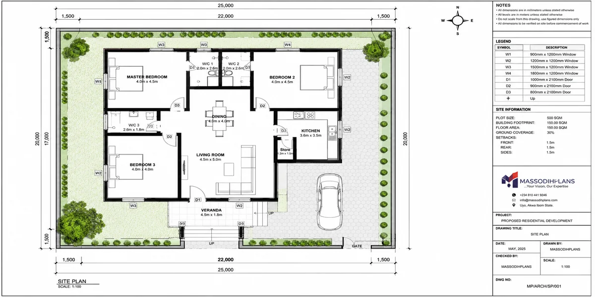
How to Design a Site Plan
How All the Drawings Work Together
Up to this point, we’ve looked at each drawing type separately site plan, floor plan, foundation, roof, elevations, sections, electrical, plumbing. But here’s the truth I want every reader to walk away with: none of these drawings exist in isolation. They’re one connected system, and a change in one always ripples through the others. Let me show you exactly how, using one real house from my practice a 3 bedroom bungalow on a 50×100 plot.
Site Plan First
Everything started here. The site plan established the plot boundary, confirmed setbacks, and positioned the building footprint on the eastern side of the plot to leave room for a driveway and garden on the west. This single decision where the footprint sits became the foundation, literally and figuratively, for every drawing that followed.
Floor Plan Follows the Footprint
With the footprint fixed by the site plan, the floor plan had to work within that exact outline. The living room ended up facing east to catch morning light, bedrooms toward the rear for privacy, and the kitchen positioned near the site plan’s confirmed driveway side for easy delivery access. Nothing in the floor plan happened by accident it responded directly to decisions already made on the site plan.
Foundation Plan Reflects the Floor Plan
Once the floor plan was locked in, the foundation plan mapped directly onto it every load-bearing wall and column position on the foundation matched precisely to the walls above. The strip foundation type chosen followed the soil report, and its layout followed the floor plan’s wall positions exactly, wall for wall.
Roof Plan Responds to the Floor Plan’s Shape
The roof plan then had to cover that exact floor plan shape. Since the floor plan had an L-shaped layout (the master bedroom wing extending slightly beyond the main block), the roof plan needed a hip-and-valley combination to properly cover both sections and manage water drainage at that internal corner a direct consequence of a floor plan decision made steps earlier.
Elevations Reveal the Floor Plan and Roof Together
The four elevations then had to accurately reflect both the floor plan below (window and door positions, exact wall lengths) and the roof plan above (pitch, ridge height, eaves). When I drew the front elevation, every window shown had to align exactly with where that window sat on the floor plan no exceptions.
Sections Tie Everything Vertically
The building section, cutting through the living room and the master bedroom wing, confirmed floor-to-ceiling heights matched between the floor plan’s room labels, the elevation’s window heights, and the roof plan’s pitch proving the whole vertical story was consistent from foundation to ridge.
Electrical Plan Follows Room Function
With the architectural drawings settled, the electrical plan mapped lighting and socket positions according to how each room in the floor plan would actually be used kitchen sockets near counters, living room lighting suited to that room’s east-facing natural light, bedroom switches positioned near each door exactly as the floor plan’s door swings dictated.
Plumbing Plan Follows Fixture Positions
Finally, the plumbing plan traced pipe routes to match the exact bathroom, kitchen, and utility positions established back in the floor plan, with soil and waste pipes routed to align with the foundation plan’s layout below.
Now Here’s Where It Gets Interesting: What Happens When One Drawing Changes
Midway through this project, the client requested one seemingly simple change: move the master bedroom’s en-suite bathroom to the opposite wall for better privacy from the hallway. Let me show you exactly how that single change rippled through the entire drawing set.
Floor Plan
First, the floor plan changed immediately the bathroom wall moved, which shifted the door position too. That change then hit the foundation plan the wall being relocated meant a load-bearing wall position shifted, requiring the foundation layout to be redrawn to match. It also affected the plumbing plan significantly since the bathroom moved to a different wall, every water supply and waste pipe route had to be redrawn, and the pipe run to the main soil stack became noticeably longer, which we then had to check against the drainage slope requirements.
Electrical Plan
The change also touched the electrical plan a light switch and socket position that had been planned near the old bathroom door location no longer made sense and had to move to the new door position. And because the bathroom’s exterior wall changed, the elevation on that side needed the window repositioned too, which meant checking the roof plan to confirm the roofline above still worked correctly with the shifted window, and reviewing the section to make sure ceiling height and window height still aligned properly at the new position.
One request. Seven drawings affected. This is exactly why, in my years of practice, I never treat a “small change” casually, and I never recommend clients make changes directly with a builder on-site without updating the full drawing set first. A change that looks simple on a floor plan can quietly break consistency across foundation, roof, elevation, plumbing, and electrical drawings if it isn’t traced through properly.
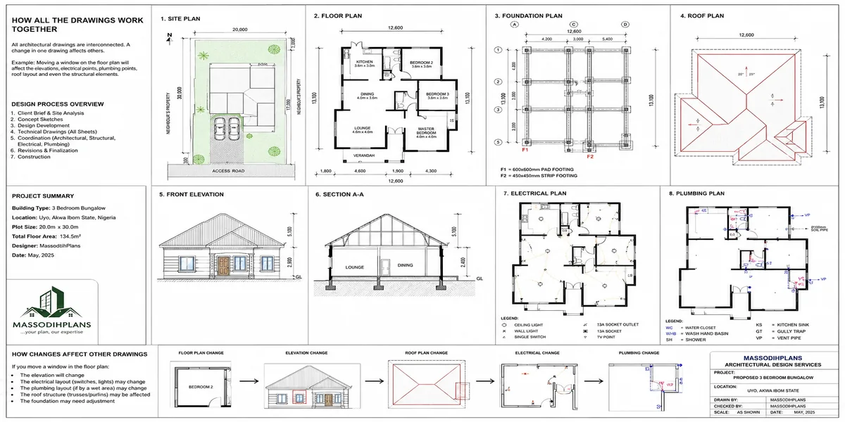
All architectural drawings work together
This is the real, practical reason a complete, coordinated house plan matters so much. It isn’t paperwork for its own sake it’s the only way to guarantee that what gets built matches what was actually designed, drawing for drawing, decision for decision. Reading a full house plan set.
Common House-Plan Mistakes
After years of designing homes and fixing other people’s plans gone wrong, I’ve noticed the same mistakes appearing again and again, no matter the country or budget. Let me walk you through the ones I encounter most, so you can spot and avoid them in your own project.
Poor Circulation
This happens when rooms are arranged without thinking about how people actually move through the house daily. I’ve seen plans where you have to walk through a bedroom just to reach a bathroom a mistake that turns a beautiful design into a daily frustration.
Tiny Rooms
Squeezing too many rooms into limited space often leaves bedrooms too small for basic furniture. I always test room sizes against real furniture layout before finalizing, exactly as we discussed.
Oversized Corridors
The opposite problem hallways wider or longer than necessary, quietly stealing square footage that could have gone into living space. Every foot of unnecessary corridor is a foot you paid to build for no real benefit.
Poor Kitchen Location
A kitchen tucked too far from the dining area, or positioned without easy access to deliveries and waste disposal, creates daily inconvenience that homeowners feel for years, not just during the design phase.
Bad Staircase Placement
A staircase positioned awkwardly can waste valuable floor space, create poor circulation, or even become a genuine safety hazard if headroom or landing space wasn’t properly checked, as we covered.
Insufficient Storage
One of the most common regrets I hear from homeowners. Storage gets treated as an afterthought, then everyone wonders why closets feel impossibly small once real life and real belongings move in.
Poor Ventilation
Rooms with only one window, or windows positioned on the same wall instead of opposite walls, block the natural cross-ventilation we discussed in Section 9, leaving rooms stuffy and overly dependent on artificial cooling.
Poor Natural Lighting
Interior rooms with no window access at all, or windows too small relative to room size, create dark, uninviting spaces a mistake that’s expensive to fix once walls are built.
Doors Clashing
Two doors that swing into each other, or a door that swings directly into a walking path, is a small detail that causes real daily annoyance something I always check carefully during the design process, as mentioned in Section 11.
Windows Incorrectly Positioned
Windows placed without considering privacy, furniture placement, or sun direction can leave a room overheated, overly exposed to neighbors, or simply awkward to furnish properly.
Plumbing Unnecessarily Complicated
Bathrooms and kitchens scattered far apart force long, complicated pipe runs, driving up both construction cost and future maintenance headaches exactly why plumbing stacking, covered, matters so much.
Roof Unnecessarily Complicated
An overly complex roof shape with too many valleys and angles looks impressive on paper but multiplies leak risk and construction cost significantly compared to a simpler, well-planned roof form.
Poor Drainage
Failing to plan how rainwater and wastewater leave the property safely is one of the most damaging long-term mistakes, often leading to foundation dampness or standing water problems that surface only after the family has moved in.
Ignoring Setbacks
Designing a footprint without first confirming legal setback requirements almost always leads to a rejected building application, forcing an expensive, frustrating redesign after the fact.
Ignoring Orientation
Placing rooms without considering sun path and prevailing wind direction, as discussed earlier, leaves homes hotter, darker, or less comfortable than they needed to be, all because orientation wasn’t studied early.
Ignoring Future Expansion
Designing only for today’s needs, with no thought toward how the family might grow, often forces costly, awkward extensions later, when a little foresight at the design stage could have made future growth simple and affordable.
Designing Before Understanding the Site
This is, in my experience, the root cause behind nearly every mistake on this list. When a design starts from a generic idea instead of the actual plot’s shape, orientation, soil, and surroundings, problems compound at every single stage that follows foundation, drainage, ventilation, and more.
The lesson across all fifteen mistakes is the same one I return to throughout this article: understand your site, plan deliberately, and never skip a step to save time early, because every shortcut here tends to resurface later as a far more expensive problem. Avoid House Plans Mistake.
How Much Does a House Plan Cost?
This is one question I get asked in nearly every consultation, and honestly, the real answer always starts the same way: “it depends.” But let me break it down properly by cost type and by country, so you get a genuinely useful picture rather than a vague answer.
Understanding the Cost Types First
Stock Plans are pre-designed, ready-made plans sold as-is, usually the most affordable option since the design work is already done and shared across many buyers.
Custom Plans are designed specifically for your plot, family, and preferences naturally more expensive since they involve dedicated design time from an architect working just for you.
Architectural Fees typically cover the design process itself concept development, floor plans, and elevations often charged as a percentage of construction cost or a flat fee depending on project size.
Structural Drawings come from a structural engineer and are usually priced separately from architectural fees, since they require independent calculations and professional liability.
MEP Drawings (mechanical, electrical, plumbing) are sometimes bundled with architectural fees, sometimes charged separately, depending on the firm and project complexity.
Site Plans are often included within a full plan package, though some providers charge separately, especially if a proper land survey is needed first.
Printing costs are usually minor compared to design fees, though large-format printing for multiple copies can add up, especially for approval submissions requiring several sets.
Professional Approval/Stamping refers to the fee charged by a licensed architect or engineer to officially certify drawings for legal submission required in most countries before construction can begin.
Modifications to an existing stock plan (resizing, mirroring, material changes) usually cost less than a fully custom design but more than buying the stock plan unmodified.
Now Let’s Look Country by Country
Nigeria
Custom architectural design fees are often calculated as a percentage of estimated construction cost, while stock plans are considerably more affordable. Structural drawings and approval processing are typically charged separately, and costs vary significantly between cities like Lagos, Abuja, and Uyo.
United States
Stock plans are widely available online at relatively affordable flat fees, while custom architect-designed homes cost considerably more, often billed as a percentage of construction cost or an hourly rate. Structural engineering and permit stamping are typically separate line items.
United Kingdom
Architect fees are commonly structured as a percentage of build cost, and full planning permission drawings add additional cost beyond basic design. Structural calculations from a chartered engineer are billed separately and are a legal requirement for most builds.
Canada
Similar to the US, stock plans offer an affordable entry point, while custom designs from a licensed architect cost more, especially in provinces requiring engineer-stamped structural drawings before permits are issued.
Australia
Custom home design fees are often higher relative to build cost compared to some other countries, reflecting strict building codes and mandatory structural engineering sign-off, particularly in cyclone or bushfire-prone regions.
South Africa
Architectural fees are frequently tiered based on project value, with SACAP-registered professionals required for approval submissions. Structural engineering is a separate, mandatory cost for most residential builds.
Ghana
Costs vary widely between Accra and smaller towns, with custom designs from registered architects costing more than informal or stock plan options, and separate fees typically applying for structural drawings and approval processing.
Kenya
Similar pattern to Ghana and Nigeria significant cost difference between Nairobi and smaller towns, with NCA-registered professionals required for official approval, and structural drawings billed separately from architectural design fees.
My Honest Advice on Cost
Here’s what 15 years of practice has taught me: the cheapest plan is rarely the cheapest house. A poorly done plan missing structural input, incomplete MEP drawings, or skipped approval stamping almost always costs more in construction delays, rework, or rejected permits than you saved on the original design fee. Always ask exactly what’s included in any quoted price: is it architectural only, or does it include structural, MEP, and approval stamping? That single question prevents most of the budget surprises I see homeowners face midway through a project. Diaspora investment and building cost guide.
House Plan vs Custom House Design
This is a question worth understanding clearly before you spend a single dollar, because choosing the wrong option here can mean paying twice once for a plan that doesn’t fit, and again for the one that actually works. Let me break down the three real paths available to you.
Ready-Made Plan
A ready-made (or “stock”) plan is a design that already exists, created once and sold to multiple buyers exactly as it is. Think of it like buying a suit off the rack the sizing is standard, not tailored to you specifically. The biggest advantage is cost and speed: you get a complete, professionally designed plan almost immediately, at a fraction of the cost of starting from scratch. The tradeoff is flexibility the layout, room sizes, and orientation are fixed, and they may not perfectly match your plot’s shape, your local climate, or your family’s specific needs.
Custom-Designed Plan
A custom plan is built entirely around you your family, your plot, your budget, your lifestyle following the full design process we walked through back in Section 11. Nothing is inherited from a previous project. This is like a tailored suit, cut specifically to your measurements. The advantage is a home that truly fits your life, your land’s orientation, and your exact requirements, with no compromise. The tradeoff is cost and time custom design takes longer and typically costs considerably more than a stock plan, since an architect is dedicating real design hours specifically to your project alone.
Modified Stock Plan
This sits comfortably in between the two. You start with an existing ready-made plan, then request specific changes resizing a room, mirroring the layout, adjusting the roof style, or adapting the design to fit a different plot size. It’s like buying that same off-the-rack suit, then taking it to a tailor for adjustments. You get much of the cost and speed advantage of a stock plan, while fixing the specific issues that don’t suit your situation. The tradeoff is that some structural or layout elements may be difficult or costly to change significantly without essentially redesigning the plan from scratch.
How I Guide Clients Through This Decision
In my own practice, I ask clients a simple question first: does your plot size and shape closely match a plan you already love? If yes, a ready-made or lightly modified plan often makes complete financial sense, and there’s no reason to spend more on a fully custom design. If your plot is unusual, sloped, oddly shaped, or your family has specific needs a standard layout can’t accommodate multigenerational living, an accessibility requirement, an unusual orientation custom design becomes genuinely worth the extra investment.
There’s no universally “better” option here. The right choice depends entirely on your specific plot, budget, and how closely your needs match what already exists. What matters most is making this decision consciously, rather than defaulting to whichever option you happened to see first.
Do You Need an Architect to Design a House Plan?
This is a question I get asked constantly, and I want to answer it honestly rather than give you a generic “yes, always hire an architect” response. The truth is genuinely nuanced, and it depends heavily on where you’re building.
Who Can Draft
Drafting simply means producing technical drawings floor plans, elevations, sections. In many places, a skilled draftsperson without formal architectural licensing can legally draft drawings, especially for smaller residential projects. Drafting skill alone, though, doesn’t guarantee good design judgment.
Who Can Design
Design goes beyond drafting it involves the full decision-making process we covered in Section 11, balancing function, aesthetics, climate, and site conditions. Many jurisdictions allow architectural designers or technologists (without full architect licensing) to legally design residential homes, particularly smaller, simpler projects, though this varies significantly by country and even by state or region within a country.
Who Can Approve
Approval is entirely a local authority function your city, municipality, or planning department reviews submitted drawings against local codes, zoning, and safety standards before issuing a building permit. No designer, however qualified, can self-approve their own plans.
Who Can Stamp/Sign
This is where licensing truly matters most. In most countries, only a licensed, registered architect or professional engineer can formally stamp or sign drawings for official submission, taking legal and professional responsibility for their accuracy and safety. This stamp is often what a building authority actually requires before granting a permit, regardless of who did the underlying design work.
Building-Permit Requirements
Every jurisdiction has its own specific permit requirements, and these can differ enormously some places require full architect-stamped drawings for any residential build, while others allow simpler homeowner-submitted drawings for small, single-storey structures below a certain size threshold.
Local Authority Requirements
Beyond stamping, local authorities often have their own additional requirements specific drawing formats, minimum information to include, or mandatory structural engineering reports. I always tell clients: contact your local planning office directly before finalizing anything, because assumptions here can cost real time and money.
Structural Engineering
Regardless of who designs the architectural layout, structural calculations almost universally require a qualified, often separately licensed, structural engineer a point I made clearly back in Section 26. Architectural design and structural engineering are two distinct professional responsibilities, even when one firm offers both services.
Professional Responsibility
This is really the heart of the matter. A licensed professional who stamps a drawing is legally and professionally accountable for it, in a way an unlicensed designer typically isn’t. That accountability matters enormously if something goes wrong structurally after construction.
My Honest, Practical Advice
Given how much this varies by location, my strongest recommendation is simple: before you finalize any house plan, contact your local building authority directly and ask exactly what’s required for approval in your specific area do they require an architect’s stamp, an engineer’s stamp, or both? Requirements in Lagos differ from requirements in London, which differ again from requirements in Toronto or Sydney.
What I can tell you confidently, based on years across this industry, is this: even where the law doesn’t strictly require an architect, involving qualified professional input especially for structural elements is rarely a place worth cutting corners. The cost of proper professional involvement is almost always smaller than the cost of fixing a serious mistake after construction has already begun.
Building Approval and Permits
Getting your house plan approved is the step that turns your drawings from an idea into a legal right to build. This process looks different everywhere, but the underlying logic is remarkably similar across most countries. Let me walk you through it.
Planning Permission
This is typically the first approval stage confirming that your intended land use (residential building) is allowed on that specific plot, and that the proposed design complies with local zoning rules, height limits, and density restrictions. In many countries, this happens before detailed construction drawings are even finalized.
Building Permit
Once planning permission is secured (or where the two are combined into one process), a building permit is the formal legal authorization to actually begin construction, based on your finalized, detailed drawings architectural, structural, and often MEP. Construction without this permit is illegal almost everywhere, regardless of how good your plans are.
Development Control
This refers to the broader regulatory framework local authorities use to manage how land gets developed across a city or region controlling density, protecting infrastructure capacity, and maintaining planned growth patterns. Your individual building permit application gets assessed within this larger framework.
Site Approval
Beyond the building design itself, some authorities separately assess the site confirming boundary accuracy, environmental suitability, access adequacy, and infrastructure availability (water, electricity, drainage connections) before granting final approval.
Professional Signatures
As discussed in Section 32, most jurisdictions require a licensed architect and/or structural engineer to sign or stamp submitted drawings, taking professional responsibility for their accuracy before the authority will even review the application.
Structural Approval
Structural drawings are frequently reviewed separately from architectural drawings, sometimes by a different department entirely, confirming the building can safely carry its intended loads based on the submitted engineering calculations.
Environmental Requirements
Depending on location and project scale, environmental considerations drainage impact, tree preservation, flood risk assessment, or proximity to protected land may require additional review before approval is granted.
Local Building Codes
Every location enforces its own specific building code minimum room sizes, ceiling heights, fire safety requirements, accessibility standards, and structural minimums. Your drawings must demonstrate compliance with these codes clearly, which is exactly why annotation and dimensioning, covered in earlier sections, matter so much at approval stage.
A Closer Look: Building Approval in Nigeria
Since I practice primarily across Akwa Ibom, Abia, Lagos, Calabar and Rivers States, Nigeria let me explain how this process typically works within the Nigerian context specifically, based on real experience guiding clients through it.
In Nigeria, building plan approval is generally handled at the state level, meaning each state Lagos, Rivers, Akwa Ibom, and others has its own Ministry of Physical Planning and Urban Development (or similarly named agency) responsible for reviewing and approving residential building plans. The process typically requires submission of a complete architectural drawing set, structural drawings prepared and signed by a COREN-registered structural engineer, a survey plan confirming the land’s legal boundaries, and evidence of land title (Certificate of Occupancy or equivalent documentation).
Architects Registration Council of Nigeria
Architectural drawings submitted for approval generally need to be prepared or endorsed by an ARCON-registered architect, since ARCON (the Architects Registration Council of Nigeria) governs professional architectural practice and signatures within the country. Similarly, structural drawings require COREN (Council for the Regulation of Engineering in Nigeria) registration for the signing engineer.
The typical approval journey involves submitting the full drawing package to the relevant state planning authority, paying required processing and approval fees, and often undergoing a site inspection to confirm the proposed building matches submitted drawings and complies with setback and zoning requirements for that specific area. Processing timelines vary considerably between states and even between local government areas within the same state, so I always encourage clients to build in a realistic buffer when planning their construction timeline around approval.
One detail I emphasize constantly with clients, especially those building from abroad and managing the process remotely: never begin construction before approval is granted, even informally or partially. I’ve seen cases where partially completed, unapproved structures faced demolition orders an outcome far more costly and painful than the delay of waiting for proper approval in the first place.
The Universal Lesson Across Every Country
Whether you’re building in Lagos, London, or Los Angeles, the underlying principle stays the same: approval exists to protect you, your neighbors, and future occupants of the building. It’s tempting to see it as bureaucratic delay, but in my experience, the approval process consistently catches real issues inadequate setbacks, structural gaps, drainage problems before they become permanent, expensive mistakes in concrete and block. Respecting this process fully is one of the most important, least glamorous parts of building a home the right way. Building Approval Checklist. Building Approval in Nigeria: Costs, Requirements, Process and How to Get Your House Plan Approved Fast
How to Modify an Existing House Plan
A stock plan rarely fits perfectly as-is, and that’s completely normal most of my clients start with a design they love and adjust it to truly fit their needs. Here’s how I approach the most common modifications.
Increasing Bedrooms
This usually means extending the footprint or converting an existing space (like an oversized living room) into an additional bedroom, always checking that plumbing and structural walls allow the change without major redesign.
Reducing Bedrooms
Often done by combining two smaller bedrooms into one larger room, or repurposing a bedroom into a home office or storage space generally simpler than adding rooms, since walls are being removed rather than added.
Moving the Kitchen
Requires careful plumbing and electrical rerouting, so I always check the new location against existing pipe and wiring runs before confirming the change is cost-effective.
Enlarging the Living Room
Sometimes achieved by removing a non-structural wall, or by extending the footprint outward if the plot allows, always keeping structural columns and load-bearing walls firmly in mind.
Adding an Ensuite
Works best when positioned close to existing bathroom plumbing lines, keeping new pipe runs short and minimizing construction disruption to unrelated parts of the house.
Adding a Balcony
Requires structural review to confirm the supporting wall or slab can safely carry the additional load, plus proper waterproofing detail where the balcony meets the main structure.
Changing the Roof
Switching roof types (say, from gable to hip) affects the roof plan, elevations, and sometimes the wall height, so I always redraw all three together rather than treating the roof as an isolated change.
Changing the Entrance
Moving the main entrance affects circulation throughout the entire floor plan, so this modification often has the widest ripple effect of anything on this list.
Adjusting to Plot Size
As covered in Section 6, this often means resizing rooms proportionally or restructuring the layout vertically rather than horizontally, depending on whether the new plot is smaller, larger, wider, or narrower.
Adding a Garage
Usually added to one side of the existing footprint, requiring updates to the site plan, driveway layout, and sometimes the roof plan to properly cover the new structure.
Adding an Annex
A separate small structure, like a self-contained unit or boys’ quarters, added elsewhere on the plot requiring its own mini design process, plus updated site plan and drainage coordination.
Every modification, however small it seems, deserves the same careful cross-check we discussed before one change rarely stays contained to a single drawing.
How to Check Whether a House Plan Is Good
After 15 years of reviewing plans both my own and ones clients bring me from elsewhere I’ve developed a simple mental checklist I run through every single time. Let me share it with you, so you can evaluate any plan with genuine confidence before committing to it.
Plot Compatibility
Does the plan’s footprint actually fit your plot’s dimensions and shape, without forcing awkward compromises?
Setbacks
Have all boundary distances been checked against your local requirements, confirmed in Section 6 and Section 9?
Room Sizes
Are rooms genuinely comfortable once real furniture is placed, not just technically “large enough” on paper?
Circulation
Can you move naturally between rooms without walking through private spaces or wasting steps on oversized corridors?
Privacy
Are bedrooms and bathrooms positioned away from public sightlines, both from the street and from neighboring properties?
Lighting
Does every room, especially interior ones, get genuine natural light rather than relying entirely on artificial lighting?
Ventilation
Do most rooms have windows on more than one wall, allowing real cross-ventilation as discussed in Section 9?
Parking
Is there enough space for your actual number of vehicles, plus reasonable guest parking if needed?
Plumbing Efficiency
Are bathrooms and kitchens grouped sensibly to minimize pipe runs, rather than scattered across the building?
Structural Practicality
Is the design realistic to build safely and affordably, without unnecessarily complex beams, cantilevers, or column arrangements?
Roof Simplicity
Is the roof shape reasonably simple, avoiding excessive valleys and angles that increase leak risk and cost, as covered in Section 23?
Drainage
Does the plan show a clear, sensible path for both rainwater and wastewater to leave the property safely?
Future Expansion
Could this design reasonably accommodate an extra room, floor, or annex later, without a complete redesign?
Construction Cost
Have you gotten a realistic cost estimate based on this specific design, rather than assuming it matches a generic “average” figure?
How I Use This Checklist Myself
Whenever I review a plan mine or someone else’s I go through this list item by item, honestly, not just glancing and assuming it’s fine. A plan that fails even two or three of these checks isn’t necessarily a bad plan, but it does mean those specific issues need addressing before construction begins, not after.
Print this list, keep it beside you, and run through it with any plan you’re considering. It’s the same discipline I bring to every project in my own practice, and it consistently catches problems before they become expensive, permanent mistakes.
House Plan Symbols and Their Meanings
Understanding symbols is like learning a new alphabet once you know it, every house plan becomes readable at a glance. Let me walk you through each one, the way I’d explain them across a table in my office.
Door
Shown as a straight line representing the door leaf, attached to a quarter-circle arc showing its swing path. The arc tells you which direction the door opens and how much floor space it needs to clear.
Window
Shown as a break in the wall line, usually with two or three thin parallel lines filling the gap. Unlike doors, windows carry no swing arc, since they don’t open into usable floor space the same way.
Stair
Drawn as a series of evenly spaced parallel lines, each representing one step, often with a directional arrow marked “UP” or “DOWN” showing which way the stairs travel between floors.
Wall
Shown as solid, thick lines, sometimes with hatching between two parallel lines. Exterior walls are typically drawn thicker than interior partition walls, reflecting their greater structural role.
Column
Represented as a small solid square or rectangle, sometimes shaded or hatched, marking a vertical structural support point that carries load from the floors above down to the foundation.
Sink
Shown as a simple rectangular or oval outline, usually positioned against a wall, sometimes with a small circle indicating the drain or tap position within the basin shape.
WC (Toilet)
Represented by a distinctive oval-on-rectangle shape — the bowl and cistern outline — instantly recognizable once you’ve seen it a few times, always positioned close to a soil pipe connection point.
Shower
Usually shown as a square or rectangle with a diagonal line or small circle inside representing the drain, sometimes with a curved line indicating the shower door or curtain path.
Electrical Outlet
Typically a small circle or square symbol with short lines extending from it, positioned along walls at socket height, sometimes labeled with a letter or number indicating circuit type.
Light
Shown as a circle, often with an “X” inside or small radiating lines, positioned on the ceiling plan at the exact fixture location, connected by a dashed line back to its switch.
Switch
Represented by a small “S” letter symbol or a distinct switch icon, usually placed near a doorway at standard reach height, connected visually to its corresponding light fixture.
Plumbing
General plumbing symbols include lines representing pipe routes, often color-coded or line-styled differently for water supply versus waste lines, paired with fixture symbols like sinks, showers, and toilets.
Section
Shown on a floor plan as a straight line with arrowheads at each end, labeled with matching letters (like “A-A”), indicating exactly where an imaginary vertical cut passes through the building.
Elevation
Represented by a small triangular marker, usually placed at the plan’s edge, pointing outward and labeled with a direction (North, South, Front, Rear) to show which exterior view corresponds to which elevation drawing.
Dimension
Shown as a straight line with arrows or tick marks at each end and a number above or beside it, indicating exact measured distance between two points on the drawing.
Level
Represented by a small triangle or circle symbol paired with a number, indicating floor height relative to a fixed reference point essential for multi-storey buildings and sloped plots.
North Arrow
A simple arrow symbol, usually placed in a corner of the site or floor plan, pointing toward true north critical for understanding sun path and building orientation, as discussed throughout this article.
Why This Dictionary Matters
Once these symbols become familiar, you’ll never look at a house plan feeling lost again. I’ve watched countless clients go from complete confusion to confidently reading their own drawings after just one walkthrough like this and that confidence changes the entire relationship you have with your project, from a passive observer to an informed decision-maker at every stage of construction.
House Plan Dimensions and Standard Room Sizes
Before I give you any numbers here, I want to be completely clear about something important: what follows are practical design guidelines based on my years of experience designing comfortable, functional homes not universal legal building codes. Actual minimum room sizes, corridor widths, and staircase dimensions are set by your local building code, and these vary significantly between countries, and even between states or municipalities within the same country. Always confirm exact minimums with your local building authority before finalizing any design. With that said, here are the practical sizes I typically work with as a comfortable, functional starting point.
Bedroom
A standard bedroom comfortably fits a bed, wardrobe, and walking space at around 10×12 ft (3×3.6m) or larger. Smaller than this, and furniture placement starts feeling genuinely tight.
Master Bedroom
I typically design master bedrooms at 14×16 ft (4.2×4.8m) or larger, allowing room for a bigger bed, additional furniture, and often direct access to an en-suite bathroom.
Living Room
A comfortable family living room usually starts around 14×16 ft (4.2×4.8m), though this scales up naturally in larger homes to accommodate more seating and entertainment space.
Dining Area
Enough space for a table and chairs with comfortable movement around them typically needs at least 10×12 ft (3×3.6m), scaling up depending on how many people the household regularly seats.
Kitchen
A functional kitchen with adequate counter space and storage generally works well starting around 10×10 ft (3×3m) for a compact layout, with larger kitchens common in bigger homes wanting an island or more counter space.
Bathroom
A full bathroom with toilet, sink, and shower or tub comfortably fits in around 6×8 ft (1.8×2.4m), while a more generous en-suite might extend to 8×10 ft (2.4×3m) or larger.
Toilet (Separate WC)
A standalone toilet room, separate from the main bathroom, can work comfortably at a compact 3×5 ft (1×1.5m), enough for the fixture plus reasonable movement space.
Corridor
I generally design hallways at a minimum of 3.5-4 ft (1-1.2m) wide for comfortable single-person movement, though wider corridors around 5 ft (1.5m) feel noticeably more comfortable in larger homes.
Staircase
A comfortable staircase typically needs a width of at least 3-3.5 ft (0.9-1m), with individual step dimensions around 10-11 inches (250-280mm) tread depth and 6-7 inches (150-175mm) riser height for safe, comfortable use.
Balcony
A functional balcony for basic outdoor seating usually needs at least 4×8 ft (1.2×2.4m), though larger balconies intended for dining or lounging often extend to 6×10 ft (1.8×3m) or more.
Garage
A single-car garage typically needs around 12×20 ft (3.6×6m) minimum, while a double garage generally requires roughly 20×20 ft (6×6m) to comfortably fit two vehicles with movement space.
Parking
An open parking space for one standard vehicle generally needs about 9×18 ft (2.7×5.4m), allowing enough room to open doors and maneuver comfortably.
Store (Storage Room)
Even a modest storage room benefits from at least 6×6 ft (1.8×1.8m), enough to hold shelving and larger household items without feeling like an afterthought.
Laundry
A functional laundry area, whether a separate room or a defined corner, generally needs around 6×8 ft (1.8×2.4m) to comfortably fit washing equipment plus a small folding or sorting space.
Veranda
A comfortable veranda for outdoor seating and relaxation typically starts around 6×12 ft (1.8×3.6m), though this scales significantly larger in warmer climates where outdoor living space matters more to daily life.
The Most Important Point in This Entire Section
Treat every number above as a practical starting guideline, not a fixed rule. Your actual room sizes should always be checked against three things: your local building code’s legal minimums, your specific plot size constraints as discussed in Section 6, and simply how the space feels once real furniture is placed in it, exactly as we tested back in Section 11’s design process. Numbers on a page are a helpful starting point but the real test of a good room size is always how comfortably it serves the people actually living in it.
House Orientation and Climate
Orientation is one of the most powerful design decisions you’ll make, and it costs absolutely nothing to get right it’s purely a matter of thoughtful planning before construction begins. Let me explain how climate should and can genuinely shape your design decisions.
Sun Path
The sun rises in the east and sets in the west, but its exact path changes with the seasons and your distance from the equator. Understanding this path for your specific location helps you decide which rooms benefit from morning light, which need protection from harsh afternoon sun, and how deep those benefits reach into the year.
Prevailing Winds
Most locations have a dominant wind direction, shifting sometimes by season. I always research this before finalizing window placement, since positioning openings to catch prevailing breezes dramatically improves natural cooling without any mechanical help.
Cross Ventilation
As covered throughout this article, placing windows on opposite or adjacent walls allows prevailing wind to move naturally through a room rather than stagnating. This single principle, applied consistently, can meaningfully reduce a home’s dependence on air conditioning.
Solar Heat
Direct sun exposure through windows, especially in the afternoon, significantly heats interior spaces. I plan window sizing and placement carefully on west-facing walls particularly, since afternoon sun there tends to be the most intense heat source in most climates.
Window Orientation
Generally, east-facing windows capture gentler morning light, west-facing windows need more careful shading due to intense afternoon sun, and south-facing windows (in the northern hemisphere) receive the most consistent daylight throughout the year though this reverses in the southern hemisphere, worth remembering for clients in Australia or South Africa.
Shading
Roof overhangs, verandas, and strategically placed trees or screens reduce direct solar heat gain without sacrificing natural light or airflow. I treat generous shading as essential in hot climates, not a decorative afterthought.
Roof Design
As discussed in Section 23, roof pitch and material affect how much heat transfers into the home below. Lighter-colored roofing and adequate ventilation space beneath the roof surface both help reduce indoor heat buildup significantly.
Outdoor Spaces
Verandas, courtyards, and covered patios extend comfortable living space beyond the interior walls, particularly valuable in warmer climates where outdoor living plays a bigger role in daily life than in colder regions.
Tropical Design
Tropical climates generally benefit from higher ceilings, larger window openings, generous roof overhangs, and layouts that maximize cross ventilation, reducing reliance on artificial cooling even during the hottest months.
A Closer Look: Nigeria and Broader African Context
In my own practice across Akwa Ibom and Rivers States, orientation and climate genuinely shape every design decision I make. Nigeria’s tropical climate, with intense sun and heavy seasonal rainfall, demands homes that manage heat and water simultaneously generous roof overhangs to shield walls from both sun and rain, elevated foundations in flood-prone areas, and window placement that prioritizes cross ventilation over large, unshaded glass expanses common in cooler climates.
Across much of West and Central Africa more broadly, I’ve found that traditional design wisdom courtyard layouts, raised foundations, deep verandas often solved these exact climate challenges long before modern materials existed, and blending that wisdom with contemporary construction techniques (as discussed in African Contemporary and Modern Nigerian styles) consistently produces the most genuinely comfortable homes for the region.
The Universal Takeaway
No matter where you’re building Lagos, London, or Los Angeles orientation and climate should shape your design from the very first sketch, not get adjusted afterward. A house that works with its climate, rather than fighting it, will always be more comfortable and more affordable to live in for decades to come.
How to Design an Energy-Efficient House Plan
Energy efficiency doesn’t need to be complicated or expensive to achieve significant results most of it comes down to smart decisions made early in the design process, many of which we’ve already touched on throughout this article. Let me bring them together specifically through an energy lens.
Orientation
As covered in Section 38, positioning your home to work with the sun path and prevailing winds, rather than against them, is genuinely the single most powerful and cost-free energy decision you can make.
Window Placement
Thoughtfully sized and positioned windows reduce reliance on artificial lighting and cooling simultaneously generous on cooler-facing walls, more controlled on walls facing intense afternoon sun.
Cross Ventilation
Effective natural airflow, discussed throughout this article, reduces or even eliminates the need for mechanical cooling in many rooms for large portions of the year.
Shading
Overhangs, verandas, and strategic landscaping block direct solar heat gain before it ever enters the building, meaningfully reducing indoor temperatures without any energy cost.
Insulation
Proper wall and roof insulation slows heat transfer in both directions keeping heat out in hot climates and retaining warmth in cooler ones directly reducing heating and cooling energy demand.
Roof Design
Light-colored roofing materials reflect rather than absorb solar heat, and adequate roof ventilation space prevents heat buildup from radiating down into living spaces below.
Daylighting
Designing rooms to maximize usable natural light throughout the day reduces dependence on artificial lighting during daytime hours, a simple principle with a real cumulative energy impact.
Solar Energy
Where budget and location allow, orienting roof sections to support solar panel installation from the very beginning avoids costly retrofitting later, and positions the home to benefit from renewable energy as it becomes more affordable.
Efficient Appliances
While not strictly an architectural decision, planning adequate space and proper electrical circuits (as discussed) for energy-efficient appliances during the design phase makes their later installation far simpler.
Water Management
Rainwater harvesting systems, efficient plumbing fixtures, and thoughtful drainage design (covered) reduce water waste and can meaningfully lower a household’s long-term utility costs.
Why This Matters More Than People Realize
Here’s something I tell every client: energy efficiency isn’t a luxury feature reserved for expensive, high-tech homes. Most of what I’ve listed above costs nothing extra beyond thoughtful planning it’s simply about making smarter decisions at the design stage rather than trying to fix inefficiency after construction is complete. A well-oriented, properly shaded, naturally ventilated home can feel dramatically more comfortable than a poorly planned one of the exact same size and budget, while costing noticeably less to run every single month for as long as the family lives there.
How to Design a Low-Cost House Plan
One of the biggest misconceptions I encounter is that a low-cost house means a poorly designed house. In truth, some of the smartest, most disciplined design work I’ve ever done has gone into stretching a tight budget as far as possible and design decisions, more than material choices, are usually what determine the final cost.
Simple Footprint
A straightforward rectangular or square footprint costs significantly less to build than complex shapes with multiple corners, wings, or angles. Every extra corner adds material, labor, and structural complexity.
Simple Roof
As discussed, a straightforward roof shape (like a basic gable) with fewer valleys and angles reduces both material waste and leak risk, compared to elaborate multi-hip designs that look impressive but cost considerably more.
Efficient Structure
Aligning walls and columns logically across floors, avoiding unnecessary cantilevers or unsupported spans, keeps structural material requirements reasonable rather than demanding expensive engineering solutions for avoidable design complexity.
Shorter Plumbing Runs
As covered, grouping bathrooms and kitchens close together, ideally stacked vertically in multi-storey homes, dramatically reduces pipe material and labor cost compared to scattered wet areas.
Reduced Corridors
Every square foot of hallway is a square foot you paid to build without adding livable space. Designing efficient circulation, as discussed, directly lowers your total construction cost.
Standard Dimensions
Using standard room sizes and structural spans that match common building material lengths (blocks, timber, roofing sheets) reduces material cutting, waste, and labor time considerably.
Material Efficiency
Choosing consistent wall heights, standard door and window sizes, and repeating similar room dimensions where possible allows for bulk material ordering and less on-site waste.
Compact Service Areas
Keeping kitchens, bathrooms, and utility spaces reasonably sized rather than oversized reduces both construction cost and long-term furnishing and fitting expenses.
Future Expansion
Perhaps counterintuitively, designing with future expansion in mind as discussed actually saves money long-term. Building a smaller, complete home now with a clear plan to add rooms later is almost always cheaper than either overbuilding today or renovating awkwardly tomorrow.
A Real Example From My Practice
I once worked with a young family on an extremely tight budget who initially wanted an elaborate multi-gabled roof and an L-shaped floor plan. By simplifying to a straightforward rectangular footprint with a basic gable roof, grouping their kitchen and bathroom on a shared wall, and designing a compact, efficient corridor, we reduced their estimated construction cost by a meaningful margin without sacrificing a single bedroom or living space they actually needed.
The Core Lesson
Low-cost design isn’t about cutting corners on quality or comfort it’s about being deliberate with every decision, eliminating waste before it ever reaches the construction site. The families I’ve helped build genuinely comfortable, low-cost homes all share one thing in common: a design that was disciplined from the very first sketch, not a budget that was simply reduced after the fact.
House Plans for Different Family Needs
No two households live the same way, and the best house plan is always the one designed around real, specific needs not a generic template. Let me discuss with you how design priorities shift across different living situations.
Single Person
Compact, efficient layouts work best a self-contained 1 bedroom design (as covered) with a functional kitchen and a comfortable living corner, prioritizing low maintenance over extra space.
Couple
A 1 or 2 bedroom home gives flexibility the second room often serves as a home office, guest space, or nursery down the line. I always ask couples about near-future plans before finalizing bedroom count.
Small Family
A 3 bedroom design, as detailed in previous Section, typically balances space and cost well for parents with one or two children, with clear zoning between shared and private areas.
Large Family
4 or more bedrooms with thoughtful zoning become essential, often requiring careful circulation planning so multiple children and parents can share the home comfortably without constant overlap in daily routines.
Multigenerational Family
As discussed in Section 15, these homes benefit from ground-floor accessible bedrooms for elderly relatives, separate living zones for privacy, and sometimes a self-contained annex for full independence within the shared property.
Elderly Occupants
Prioritize single-level living where possible, wider doorways, step-free entries, and bathrooms designed for safety and accessibility details I always plan in from the start rather than retrofitting later, exactly as emphasized.
Families With Children
Open sightlines from kitchen or living areas to play spaces matter enormously for supervision, along with durable, easy-to-clean finishes and enough storage for the inevitable accumulation of toys and school items.
Rental Property
Designs prioritizing simple, durable finishes, efficient plumbing stacking, and layouts that appeal broadly to different tenant types tend to perform best financially over time.
Student Accommodation
Often benefits from a self-contained or shared arrangement with multiple compact bedrooms, shared kitchen and living facilities, and durable, low-maintenance materials suited to higher turnover occupancy.
Guest Accommodation
A dedicated guest room or self-contained guest suite, as discussed, gives visitors genuine privacy and comfort without disrupting the main household’s daily routine.
The Common Thread
Across every single one of these scenarios, the underlying principle holds true: start with who will actually live in the home, how they’ll use each space day to day, and let that reality guide every design decision that follows. A house plan copied without considering the real household behind it almost always creates friction somewhere whether that’s insufficient privacy, poor accessibility, or simply rooms that don’t match how the family actually lives. Design for the people first, and the right layout tends to reveal itself naturally.
House Plan Design Case Studies
Theory is useful, but nothing teaches better than real projects. Let me take you through four actual cases from my practice, showing the complete journey from first conversation to final drawing.
Case Study 1: How I Designed a 2-Bedroom House on a 50×100 Plot
A young couple came to me with a generous 50×100 plot but a modest budget, wanting a 2 bedroom home with room to grow. Client requirements centered on a master bedroom, a flexible second room for a future nursery, and a proper living-dining area for entertaining family.
Studying the site, I found the plot faced east with good road access but a slight slope toward the rear. The concept prioritized a single-storey layout to control cost, with bedrooms grouped on the quieter western side away from street noise.
My rough sketches tested two options one with bedrooms side-by-side, another separated by the family bathroom as a buffer. The client preferred the second, exactly the reasoning we walked through. Moving into AutoCAD, I finalized exact dimensions: a 14×15 ft master bedroom, an 11×12 ft second bedroom, and a combined 20×14 ft living-dining space.
The final drawings included full plumbing stacking between the kitchen and bathroom, and a slightly raised rear section to address the site’s natural slope without expensive earthworks. The client moved in eighteen months later, and the second bedroom is now their nursery exactly as planned from day one. Here is the Drawings:
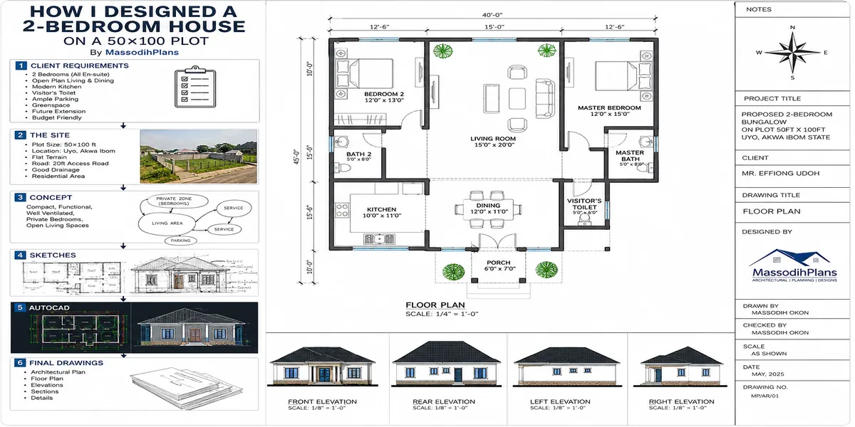
2 bedroom on 50×100 plot size design process
Case Study 2: How I Designed 4 Self-Contained Units on One Plot
An investor client wanted maximum rental income from a 60×100 plot, requesting four independent self-contained units, each following the principles covered before. Requirements were simple but firm: each unit needed its own entrance, bathroom, kitchenette, and clear separation from neighboring units.
Studying the site, I noted the plot’s width comfortably allowed a two-row arrangement, two units facing the street and two facing the rear, connected by a shared but clearly divided access path. The concept stage focused entirely on privacy ensuring no unit’s windows faced directly into another’s living space.
Rough sketches tested unit sizing at roughly 300 sq ft each, the minimum practical arrangement discussed. In AutoCAD, I finalized identical, mirrored layouts for efficiency, deliberately stacking each unit’s kitchen and bathroom plumbing along a shared central service wall, cutting significant plumbing cost across all four units.
The final drawings included a shared but well-screened parking area and individual electrical metering points per unit a detail the client specifically requested for straightforward tenant billing. The project delivered exactly the rental income structure the investor needed, built on a foundation of genuinely private, comfortable individual units.
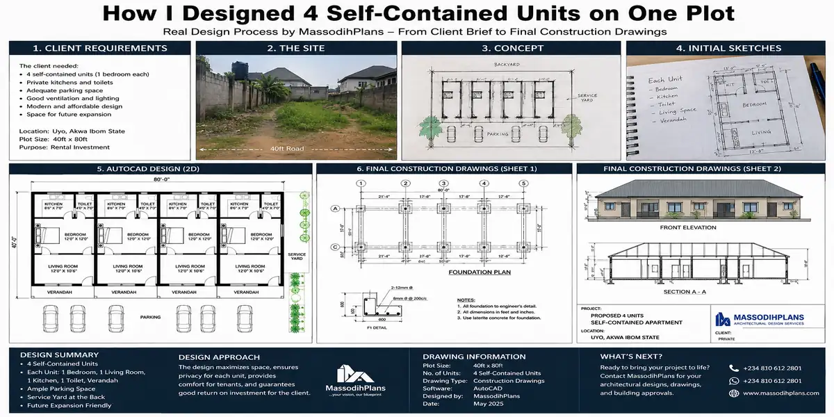
Self contained House plans design
Case Study 3: How I Converted a Client’s Sketch Into a Professional Floor Plan
A diaspora client sent me a rough pencil sketch on paper, drawn from memory of the family home she grew up in, wanting something similar for her own retirement plot back home. Her requirements were emotional as much as practical she wanted specific room relationships preserved from her childhood memory.
Studying her sketch carefully, I identified the core relationships she valued: a central living room connecting directly to a covered veranda, and a kitchen positioned within calling distance of the dining area. The concept stage involved translating her intuitive, imprecise sketch into realistic, buildable proportions.
My rough sketches tested her rooms against practical dimensions, adjusting sizes that her original sketch had drawn disproportionately. In AutoCAD, I built the accurate floor plan, preserving every relationship she described while correcting structural feasibility issues her hand-drawn version hadn’t considered.
The final drawings captured her memory faithfully while being fully buildable she told me the finished floor plan brought her to tears, because it genuinely felt like home.
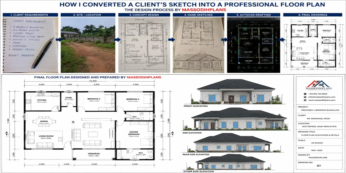
How I Converted a Client’s Sketch Into a Professional Floor Plan
Case Study 4: How I Redesigned a Poor Floor Plan
A client arrived with a plan from another provider already approved for construction, but something felt wrong to her. Reviewing it against the checklist, I found several of the mistakes covered a bathroom accessible only through a bedroom, an oversized central corridor wasting nearly 80 sq ft, and windows poorly positioned for cross ventilation.
Working from her original requirements, I restructured circulation entirely, eliminating the wasted corridor and repositioning the bathroom with independent hallway access. The concept preserved her approved footprint and room count, exactly as needed to avoid a new approval process, while completely reworking the internal arrangement.
The final drawings solved every issue on the original checklist without changing the building’s external footprint at all proof that a poor floor plan isn’t always a matter of size or budget, but often simply a matter of thoughtful arrangement.
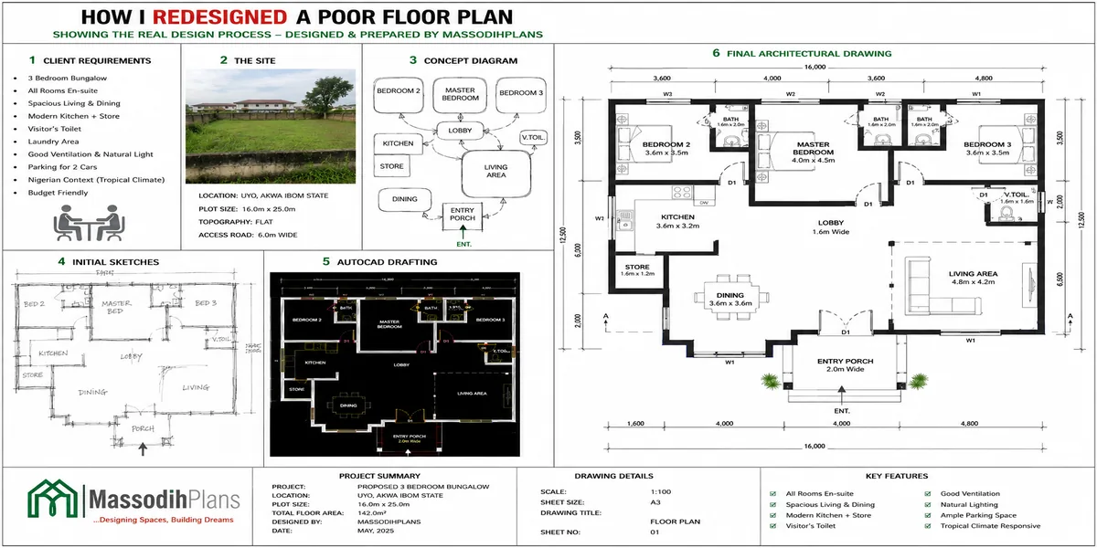
How to redesigned a poor floor plans process
Frequently Asked Questions About House Plans
Let me answer the questions I hear most often, gathered directly from years of client conversations and consultations.
What is a house plan?
A house plan is the complete set of drawings showing how a home will be built floor layout, elevations, structural details, and more as we covered fully in Section 1.
What is the difference between a house plan and a floor plan?
A floor plan is just one drawing within a full house plan, showing room layout from above. A house plan includes the floor plan plus elevations, sections, roof plan, and service drawings, as explained in Section 1.
What drawings are included in a house plan?
A complete package includes site plan, floor plans, foundation plan, roof plan, elevations, sections, electrical layout, plumbing layout, and schedules the full breakdown is in Section 2.
How much does a house plan cost?
Cost varies significantly by country and whether you choose a stock or custom plan, covered in detail with country-specific figures in Section 30.
Can I modify a house plan?
Yes, most stock plans can be modified resizing rooms, mirroring layouts, or adjusting for a different plot, as explained in Section 34.
Can I design my own house plan?
Technically you can sketch your own ideas, but translating that into a safe, buildable, approvable design requires professional input, especially for structural elements, as discussed in Section 32.
Do I need an architect?
It depends heavily on your local jurisdiction’s requirements some places mandate licensed sign-off, others don’t for smaller projects. Full details are in Section 32.
What size should a bedroom be?
A comfortable standard bedroom is generally around 10×12 ft, though this is a design guideline, not a legal minimum see Section 37 for the complete breakdown.
How do I choose a house plan?
Consider occupants, budget, plot size, climate, and future needs together, exactly as walked through step by step in Section 9.
How do I read a floor plan?
Learn the basic symbols walls, doors, windows, dimensions covered thoroughly with a real annotated example in Section 10.
How do I draw a floor plan?
Follow a structured process from understanding requirements through to a finished, checked layout, exactly as demonstrated in Section 11.
What is an elevation?
An elevation is a flat, to-scale exterior view of one side of your building, explained fully with the design process in Section 21.
What is a section?
A section is a “sliced” vertical view showing what’s happening inside the building from foundation to roof, covered in Section 22.
What is a roof plan?
A roof plan shows the roof’s shape, pitch, and drainage strategy, with all major roof types explained in Section 23.
What is a foundation plan?
It shows what’s beneath the ground floor footings, foundation walls, and structural support — explained alongside the architect-engineer distinction in Section 26.
What is an electrical plan?
A drawing showing lighting, switches, sockets, and circuit routing throughout the home, covered in full in Section 24.
What is a plumbing plan?
A drawing tracing water supply, waste, and drainage routes through the house, explained completely in Section 25.
Can a house plan fit my plot?
Sometimes with modification, sometimes not Section 6 explains how plot dimensions shape what’s realistically achievable.
How do I design for a small plot?
Focus on vertical development, light wells, and efficient footprints, exactly as detailed in Section 19.
Can one house plan be adapted to another country?
Often yes for layout and style, but always confirm local building codes, climate suitability, and approval requirements first differences discussed throughout.
Have a question we haven’t covered here? Feel free to reach out directly helping people avoid these exact confusions is the entire reason this article exists.
Free Resources to Help You Get Started
Everything we’ve covered in this article is meant to genuinely help you, not just inform you. So to make it practical, I’ve put together a set of free resources drawn directly from the checklists and principles discussed throughout this piece.
You can grab our House Plan Checklist, built evaluation framework, to confidently assess any plan before committing to it. Our Floor-Plan-Reading Checklist walks you through the symbols covered, so you can confidently interpret drawings on your own. If you’re still deciding on room proportions, our Room-Size Guide expands on the practical dimensions shared.
For visual learners, our House-Plans Selection and Symbols PDF turns the visual dictionary from Section 36 into a printable, easy-reference sheet you can keep beside you while reviewing any drawing. Our Home Owner’s Construction Checklist captures the full 15-step process, so you can follow along step by step on your own project.
If you’re navigating approvals, our Building-Materials Checklist and Site-Planning Checklist bring together the requirements discussed, helping you prepare a complete, submission-ready package. And before you even purchase land, our Land-Buying Checklist covers the plot considerations that too many buyers only discover after it’s too late to change course.
Finally, our Construction Budget Template helps you plan realistically around the cost factors discussed, so surprises stay to a minimum.
Beyond these free tools, if you’re ready to move from planning to building, our Plans Library offers fully detailed, ready-to-use house plans across the styles, sizes, and configurations covered throughout this article and our Plan School goes deeper still, for anyone wanting to genuinely understand this craft, not just receive a finished drawing.
Need a House Plan Designed for Your Plot?
If everything we’ve covered in this article has confirmed one thing, I hope it’s this: a well-designed house plan is never a luxury it’s the foundation of a home that genuinely works for your family, your land, and your budget for decades to come.
This is exactly the kind of work I do every day. Whether you’re starting completely from scratch or need to fix a plan that isn’t quite right, here’s how I can help:
I offer full concept design, translating your requirements and site conditions into an initial design direction, exactly as walked through. From there, I prepare complete architectural drawings, including detailed floor plans, all four elevations, and building sections that tie the whole design together vertically, as covered.
I also handle roof plans and site plans, ensuring your drainage, orientation, and plot layout are properly coordinated from the start. For technical coordination, I prepare electrical layouts and plumbing layouts, planned the way we discussed efficient, safe, and genuinely practical.
All drawings are professionally produced through AutoCAD drafting, delivering accurate, construction-ready plans your builder can trust completely.
If you already have a plan that isn’t quite fitting your needs, I offer plan modifications resizing, adapting, or reworking layouts as discussed. I also specialize in small-plot design, helping you get the most out of a tight or unusually shaped piece of land, and multi-unit designs, whether for rental income or extended family housing, as shown in Case Studies.
If you’d like help with your own project, I’d genuinely love to hear about your plot and your family’s needs. Reach out to me directly through okonmassodih@gmail.com, WhatsApp: 07013315491, or the contact page on MassodihPlans.com and let’s talk through what would work best for your home.
Conclusion
We started this guide with a client handing me a folded, messy sketch, asking if it even counted as a house plan. Forty-five sections later, I hope you now know the honest answer: a real house plan is never just one drawing. It’s a complete, coordinated system floor plans talking to foundations, elevations matching sections, electrical and plumbing lines following the same logic as the rooms they serve. Every section in this guide was built to show you that connection, piece by piece, the same way I walk every client through it in my own office.
If there’s one thing I want you to carry away from everything we’ve covered, it’s this: good design isn’t about following trends or copying a beautiful photo you saw online. It’s about understanding your plot, your climate, your family, and your budget deeply enough that the house you build actually serves your real life not just the day it’s finished, but for decades after.
I’ve shared real projects, real mistakes, real measurements, and fifteen years of lessons learned the hard way, so you don’t have to learn them the same way. That’s the entire purpose behind MassodihPlans not chasing search rankings, but genuinely solving the confusion so many people face before they ever break ground.
Wherever you are in your journey still choosing a plot, comparing floor plans, or ready to start drawings you now have a real foundation to build from. Explore our Plans Library for ready-made designs, our Plan School to keep learning, or reach out directly if you’d like a plan designed specifically for your land.
Your home starts with understanding it. Now you do.