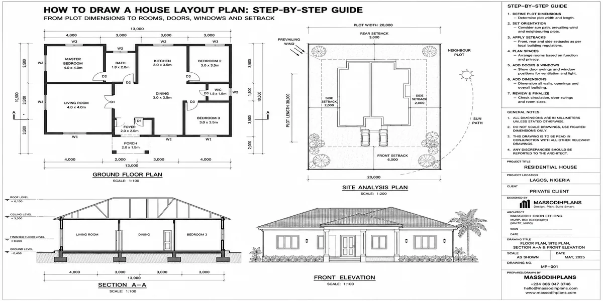
How to Draw a House Layout Plan: Step-by-Step Guide From Plot Dimensions to Rooms, Doors, Windows and Setback
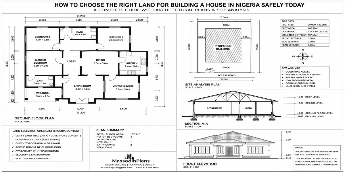
Take a plot of 15 metres by 30 metres. Before you draw a single wall, roughly 100–150 square metres of that plot is already unavailable to you swallowed by setbacks you’re legally required to leave on every side. Most “how to draw a house plan” tutorials skip straight to sketching rooms and never mention this, which is exactly how beginners end up designing a beautiful layout that doesn’t actually fit their land.
This guide fixes that gap. We’ll go in the actual order a layout plan needs to be built: plot dimensions first, setbacks second, then rooms, doors, and windows with a full worked example on a real plot size so you can see every calculation, not just read about it in the abstract. By the end, you’ll be able to take your own plot dimensions and produce a proportioned, buildable rough layout and know exactly where a hand-drawn sketch needs to hand off to a professional.
What You Need Before You Start
Your plot’s survey plan (dimensions and orientation), or accurately measured dimensions if a survey isn’t available yet
Graph paper (5mm or 1cm grid) or a simple 2D floor planning tool both are covered below
A ruler, pencil, and eraser (for hand-drawing) trial and error is normal at this stage, not a sign you’re doing it wrong
A list of the rooms you need and, ideally, a rough sense of your budget ceiling, since floor area drives cost directly
Your local planning authority’s setback and plot-coverage requirements for your specific area, since these vary by state and even by zoning classification within a state
Get your setback figures confirmed by your local planning authority before you draw anything, not after. Assuming a standard setback and discovering later that your area requires more is one of the most common and most frustrating beginner mistakes.
Step 1: Establish Your Plot Dimensions and Orientation
Start with the actual shape of your land, not an assumed rectangle. Note the exact length of each boundary, the direction of true north, and where the road or street frontage sits. Orientation isn’t a formality it determines which side of your house gets harsh afternoon sun and which side is sheltered, and that should influence where you place bedrooms versus living spaces later.
Worked example plot: We’ll use a 15m x 30m plot (450 sqm) fronting a road on its 15m side, which is one of the most common plot dimensions issued in Nigerian residential layouts. Mark this rectangle to scale on your graph paper first if you’re using 1cm = 1m, that’s a 15cm x 30cm rectangle.
Step 2: Apply Setbacks to Find Your Buildable Area
This is the step almost every generic “how to draw a house plan” tutorial skips, and it’s the one that actually determines how much house you can build.
Setback requirements vary by state, local planning authority, and zoning classification, but common Nigerian residential minimums are approximately:
- Front setback: 3.0m – 6.0m from the road boundary
- Side setbacks: 1.5m – 3.0m from each side boundary
- Rear setback: 3.0m from the rear boundary
These figures are common ranges, not universal rules. Setback requirements differ by state and by your plot’s specific zoning classification, and some local authorities apply larger setbacks for corner plots or plots above a certain size. Always confirm exact figures with your local planning authority before finalizing a layout.
Worked example, continued: Applying a front setback of 4.5m, side setbacks of 1.5m each, and a rear setback of 3m to our 15m x 30m plot:
- Buildable width: 15m − (1.5m + 1.5m) = 12m
- Buildable depth: 30m − (4.5m + 3m) = 22.5m
- Maximum buildable footprint: 12m x 22.5m = 270 sqm
Now apply your plot coverage limit commonly 40–50% of total plot area for residential zoning in many areas. On a 450 sqm plot at 45% coverage, your actual maximum ground-floor footprint is 202.5 sqm, meaning even within the 270 sqm setback-cleared area, you won’t fill all of it you’ll leave room for parking, a garden strip, or a two-storey design that keeps the footprint smaller while adding floor area upstairs.
This is the number you actually design rooms against not the plot size, and not the setback-cleared area, but the plot-coverage-limited footprint.
Step 3: List Your Rooms and Assign Rough Areas
Before drawing anything further, list every room you need and give each one a realistic minimum area based on function, not guesswork:
- Living room: 20–30 sqm
- Dining area: 12–16 sqm
- Kitchen: 10–15 sqm
- Master bedroom (with en-suite): 18–24 sqm including bathroom
- Standard bedroom: 12–15 sqm
- Bathroom (standard): 4–6 sqm
- Staircase (if two-storey): 8–10 sqm of footprint per floor
- Corridors/circulation: budget 8–12% of total floor area, not more
Add these up and compare the total to your available footprint from Step 2. If your room list exceeds your buildable footprint, this is the point to trim room sizes or go to a second storey not after you’ve already sketched a layout you’re emotionally attached to.
Worked example, continued: For a 4-bedroom single-storey home on our 202.5 sqm footprint: living (25) + dining (14) + kitchen (12) + master bedroom with en-suite (22) + 3 standard bedrooms (13 x 3 = 39) + 2 shared bathrooms (5 x 2 = 10) + kitchen store (4) + circulation (roughly 10% = 20) totals approximately 146 sqm comfortably within the 202.5 sqm limit, leaving room for a veranda and slightly more generous circulation if desired.
Step 4: Draw a Bubble Diagram Before You Draw Walls
A bubble diagram is a rough circle-and-label sketch showing which rooms sit near which no walls, no measurements, just relationships. This step exists to solve your layout’s logic before you invest time in precise drawing.
Group rooms by zone:
- Public zone: living room, dining area, guest powder room placed near the entrance
- Service zone: kitchen, store, laundry placed adjacent to the dining area but with its own access if possible
- Private zone: bedrooms and bathrooms placed furthest from the entrance for privacy and quiet
Draw arrows between bubbles that need direct connection (kitchen to dining, entrance to living room) and note which rooms should NOT be adjacent (a bedroom bubble should never sit directly against the kitchen, both for noise and for cooking-smell reasons).
Spend real time on the bubble diagram stage it’s the cheapest place to fix a bad layout. Moving a bubble on a rough sketch costs nothing. Moving a finished wall costs money and time.
Step 5: Convert the Bubble Diagram Into a Scaled Outline
Now translate your bubble diagram onto your scaled graph paper, using your buildable footprint from Step 2 as the outer boundary.
Choose and stick to one scale throughout 1:100 (1cm on paper = 1m on the ground) is the most practical for a full house layout on standard paper; 1:50 works better if you’re focusing on one section in more detail. Draw the outer wall line first as a rectangle (or your actual footprint shape) matching your buildable dimensions, then divide the interior into rooms based on your bubble diagram’s zoning, adjusting each room’s boundary until its area roughly matches the target you set in Step 3.
This will not be right on the first attempt, and that’s normal. Expect to redraw the internal divisions two or three times as room proportions and the overall flow settle into something workable.
Step 6: Draw Walls With Actual Thickness
A common beginner mistake is drawing walls as single thin lines with no thickness, which quietly overstates how much usable floor area you actually have. Standard Nigerian residential wall thickness is typically:
- External walls: 225mm (9 inches, a full block width)
- Internal partition walls: 150mm (6 inches, a half block width) is common, though some designers use 225mm throughout for better sound insulation
Draw walls as double lines with this thickness represented at your chosen scale, not single lines at 1:100 scale, a 225mm wall is drawn as a 2.25mm-thick double line. This matters because wall thickness eats into your usable room area, and skipping it at the sketch stage is a common reason beginner layouts feel tighter once actually built than they appeared on paper.
Step 7: Place Doors Rules That Actually Matter
Door placement has real functional rules, not just aesthetic ones:
Standard door sizes: internal doors are typically 800mm–900mm wide; the main entrance door is typically 900mm–1000mm wide; bathroom doors can be as narrow as 700mm
Swing direction: doors should swing into the room they serve (not out into a corridor, where they become an obstruction), and should never swing into a path that blocks another door or a fixed fixture like a wardrobe
Door placement near corners: avoid placing a door hinge directly at a wall corner leave at least 100–150mm of wall between the door frame and an adjacent perpendicular wall, so the door can open a full 90 degrees without obstruction
Passage width: any corridor formed between two door swings must remain a clear passage never let one door’s swing arc overlap another door’s swing arc
On your scaled drawing, represent each door as a quarter-circle arc showing its swing direction, opening from the wall line this is standard architectural symbol convention and lets anyone reading the plan immediately understand how each room is accessed.
Step 8: Place Windows — Sizing for Function, Not Just Light
Window placement should be driven by two functional requirements before aesthetics: daylight and cross-ventilation.
Minimum window area for habitable rooms is commonly guided at around 10% of the room’s floor area for adequate daylight a 15 sqm bedroom should have at least roughly 1.5 sqm of window area
Cross-ventilation requires openings on at least two walls of a room wherever possible a room with windows on only one wall will always feel more stagnant than one with openings that let air pass through
Standard window sizes in Nigerian residential construction commonly range from 900mm x 1200mm for bedrooms to 1800mm x 1200mm or larger for living rooms, though exact sizing should match the room’s proportions and your facade design
Sill height: bedroom and living room windows are typically set with a sill height of 900mm–1000mm from finished floor level; kitchen windows are often set higher, around 1200mm, to clear counter height
On your drawing, represent windows as a break in the wall line with a thin double line across the opening distinct from the door’s arc symbol so the two are never confused when the drawing is read later.
Window and door placement affects furniture layout more than beginners expect a window centered on a wall you intended for a wardrobe, or a door swing that blocks where a bed would naturally sit, are both avoidable with a five-minute furniture check at the sketch stage, before they’re locked into a working drawing.
Step 9: Check Circulation and Flow
With rooms, walls, doors, and windows roughly in place, walk through your drawing on paper the way you’d actually walk through the house:
From the main entrance, can you reach the living room, kitchen, and each bedroom without cutting through another private room?
Does any bedroom require passing through another bedroom or the kitchen to reach a bathroom?
Is there a clear, direct path from the kitchen to the dining area that doesn’t cross the main circulation route from the entrance?
Are there any dead-end pockets of space created by how rooms were divided awkward leftover areas serving no function?
If any of these checks fail, this is the point to adjust moving a wall by 300mm on a rough sketch is trivial; discovering the same flow problem after foundation work has started is not.
Step 10: Add Dimensions, Labels, and a Symbol Legend
A layout plan isn’t complete, even at rough-sketch stage, without:
- Dimension lines on all external walls and major internal walls, showing exact lengths in metres or millimetres, placed outside the drawing’s outline to avoid clutter
- Room labels with each room’s name and calculated area (e.g., “Master Bedroom 18.5 sqm”)
- A north arrow, so orientation is unambiguous to anyone reading the plan later
- A simple symbol legend explaining your door-swing arcs, window breaks, and any other symbols used, so the drawing is readable without you standing there to explain it
Full Worked Example: From Plot to Rough Layout
Bringing every step together on our 15m x 30m plot:
- Plot: 15m x 30m (450 sqm), road frontage on the 15m side
- Setbacks applied (4.5m front, 1.5m sides, 3m rear): buildable area reduces to 12m x 22.5m
- Plot coverage limit at 45%: maximum footprint 202.5 sqm
- Room list totals approximately 146 sqm for a 4-bedroom single-storey layout, leaving roughly 56 sqm of buffer for a veranda, wider circulation, or a slightly larger living area
- Bubble diagram: entrance leads into living/dining (public zone) near the front; kitchen and store sit adjacent to dining (service zone) with a rear or side service entrance; the four bedrooms and two bathrooms cluster toward the rear and one side (private zone), furthest from the main entrance
- Scaled outline drawn at 1:100 on graph paper, matching the 12m x 22.5m buildable footprint
- Walls drawn at 225mm external, 150mm internal
- Doors placed with correct swing direction, none blocking another opening
- Windows placed on at least two walls per habitable room, sized to roughly 10%+ of each room’s floor area
- Circulation checked: entrance leads to living room directly; kitchen accessible from dining without crossing bedroom zone; no bedroom requires passing through another room to reach a bathroom
- Dimensions, room labels, north arrow, and symbol legend added
That sequence not “sketch rooms until it looks right” is what actually produces a layout that fits your land, meets basic functional rules, and gives a professional a genuinely useful starting point rather than a rough idea to redo from scratch.
Hand-Drawing vs. Simple Software: Which Should You Use?
Hand-drawing on graph paper is the better starting point for genuine beginners. It forces you to think through proportions and relationships directly, it costs nothing, and mistakes are cheap you redraw a section, not restart a file. Every step above works identically on paper.
Simple 2D floor planning software becomes useful once you’ve done at least one rough hand sketch and want to refine it most beginner-friendly tools let you drag walls, doors, and windows with automatic dimensioning, which speeds up the trial-and-error phase considerably. They are a refinement tool, not a substitute for understanding the setback and room-sizing logic covered above software will happily let you draw a layout that violates your setbacks or plot coverage limit if you don’t check those numbers yourself first.
Common Beginner Mistakes to Avoid
Skipping the setback calculation entirely and designing against the full plot size, then discovering the layout doesn’t legally fit
Drawing walls as single lines with no thickness, overstating usable floor area
Placing a bedroom directly adjacent to the kitchen, creating noise and odour problems
Door swings that block another door or a wardrobe, discovered only once furniture is moved in
Windows on only one wall of a room, producing poor ventilation despite adequate window area
No circulation check, resulting in a layout that requires walking through one bedroom to reach another room
When to Hand This Off to a Professional
A rough layout plan built through this process is genuinely useful it clarifies your brief, catches obvious problems early, and gives an architect a real starting point instead of a vague description. It is not, however, a substitute for professional drawings. Structural design (foundation type, column and beam sizing), accurate compliance with your specific local setback and coverage regulations, and the electrical/plumbing layers all require a registered architect and structural engineer, and in most jurisdictions, plan approval requires drawings prepared and stamped by qualified professionals before construction can legally begin.
Think of everything above as the step that makes your conversation with an architect faster and more precise not as a replacement for that conversation.
Frequently Asked Questions
Can I draw my own house layout plan without any architecture background?
Yes, a rough layout following the process above is entirely achievable as a beginner. It should still be reviewed, refined, and formally drawn by a registered architect before construction, particularly for structural and approval-compliant drawings.
What scale should I use for a house layout plan?
1:100 is the most practical scale for a full house layout on standard paper. Use 1:50 if you want to focus on one area in more detail.
How much of my plot is actually lost to setbacks?
It depends on your plot size and local setback requirements, but on a typical residential plot, setbacks and plot coverage limits combined often remove 50–60% of total plot area from your buildable footprint which is why calculating this first, before designing rooms, is essential.
What is the minimum size for a bedroom in a house layout?
A standard bedroom is typically planned at 12–15 sqm, and a master bedroom with an en-suite bathroom at 18–24 sqm, though local minimums can vary and larger is always preferable where the plot allows.
Do I need to know the exact setback rules for my area before I start drawing?
Yes. Setback and plot coverage requirements vary by state and zoning classification, and designing without them risks a layout that cannot legally be approved as drawn confirm these figures with your local planning authority before Step 2.
Conclusion
A house layout plan that actually works is built in a specific order plot and setbacks first, room list and zoning second, then walls, doors, and windows layered on with functional rules, not guesswork. Follow that sequence and even a rough hand-drawn sketch will give you (and any architect you bring in afterward) something genuinely usable, rather than a pretty drawing that has to be redone from scratch once it meets real plot dimensions and planning requirements.
If you want a head start rather than drawing from a blank page, browse our Plans Library for ready layouts across common Nigerian plot sizes, or visit Plan School for more plan-reading and drawing guides like this one. When you’re ready to turn a rough layout into approved, buildable drawings, our Services page outlines how we take a project from concept through approval. You can also explore more building guides on our Homepage.
Related Guides
- Semi-Detached House Plans: Modern Duplex and Bungalow Designs With Shared Walls, Dimensions, Costs and Layout Ideas
- Courtyard House Plans: Beautiful 2–6 Bedroom Designs With Private Outdoor Spaces, Floor Plans and Dimensions
- Contemporary House Plans: Modern 2–6 Bedroom Designs With Open Layouts, Large Windows, Dimensions and Costs
- House Finishing Cost in Nigeria: Complete Breakdown of Tiles, Painting, Ceiling, Doors, Plumbing and Electrical Work
- Foundation Cost Calculator: Estimate House Foundation Cost From Soil Type, Dimensions, Materials and Labour
- Block Quantity Calculator: How to Calculate the Number of Blocks Needed for Any House From Your Floor Plan
- Cement Quantity Calculator for Building: Calculate Bags Needed for Foundation, Blockwork, Slab, Plastering and Screeding
- Self-Contained House Plans: 15 Efficient Designs With Room Dimensions, Floor Plans, Building Costs and Ideas
- 1 Bedroom House Plan: Affordable Self-Contained Floor Plans With Dimensions, Materials, Cost and Space-Saving Ideas
- 6 Bedroom House Plans: Modern Nigerian Floor Plans With Dimensions, Ensuite Rooms, Parking and Cost Estimates
Author
Massodih Okon is a Nigerian built-environment professional with academic and professional experience in urban and regional planning, geography, architectural design, Landscape Design, GIS and land development.
He holds a Master’s degree in Urban and Regional Planning from the University of Uyo and a first degree in Geography and Regional Planning.
Through MassodihPlans, he publishes practical guides on Nigerian house plans, building design, physical planning, site planning, development approval and residential construction. Read the full author profile →