Best Scale for House Plan Drawing in Nigeria
Use 1:100 for the floor plans, elevations and sections of an ordinary house when you are submitting for approval. Use 1:50 for the working drawings your builder will use, and for any house on a half plot or smaller where every 100 mm counts. Draw the site plan at 1:200, or 1:100 if your plot is small enough to fit on the sheet. Draw details like the staircase, door frames and wall sections at 1:20, 1:10 or 1:5. Before you draw anything, ask your state planning authority whether it sets the scale itself, because some do.
That answer takes ten seconds to read, and it is the least important thing in this article. Here is what actually costs people money. A designer draws a perfect 1:100 plan on an A1 sheet. A client prints it on A3 at a business centre with “fit to page” ticked. The scale printed in the title block still says 1:100, but the paper now says 1:200. The bedroom that should be 3.6 m wide measures 18 mm on the print. The contractor lays his 1:100 ruler on it, reads 1.8 m, and a very confused conversation starts on site.
So stay with me to the end. I will show you how to pick a scale using a formula instead of guessing, how to fit any plot on any sheet, and how to catch a wrong scale on someone else’s drawing in ten seconds with nothing but a ruler. Since this is MassodihPlans, I will also show you what changes when your plot is small, because small plots are where scale mistakes hurt most.
The Quick Answer, in One Table
Let me give you the cheat sheet first, then we will go through the reasoning so you can adjust it for your own plot.
| Drawing | Best scale | Why this scale |
|---|---|---|
| Location plan (where the plot sits in the area) | 1:500 to 1:2500 | Shows roads and landmarks, not rooms |
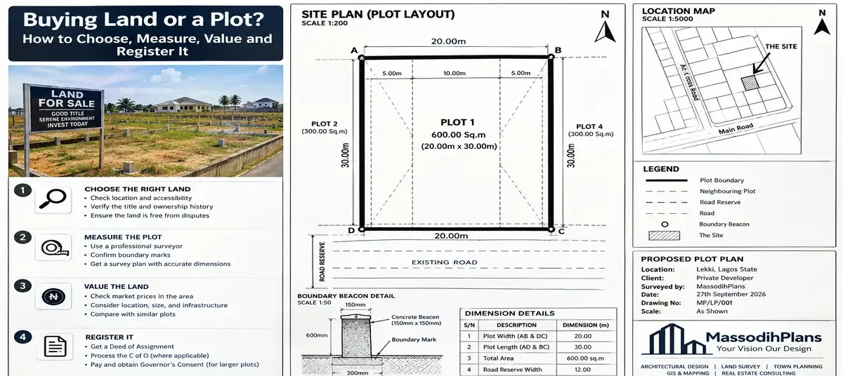
| Site plan (plot, house, setbacks, fence, gate) | 1:200 (1:100 for small plots) | Shows the building line and boundaries clearly |
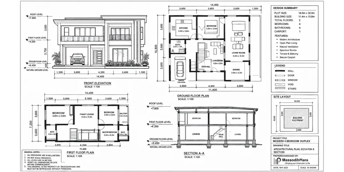
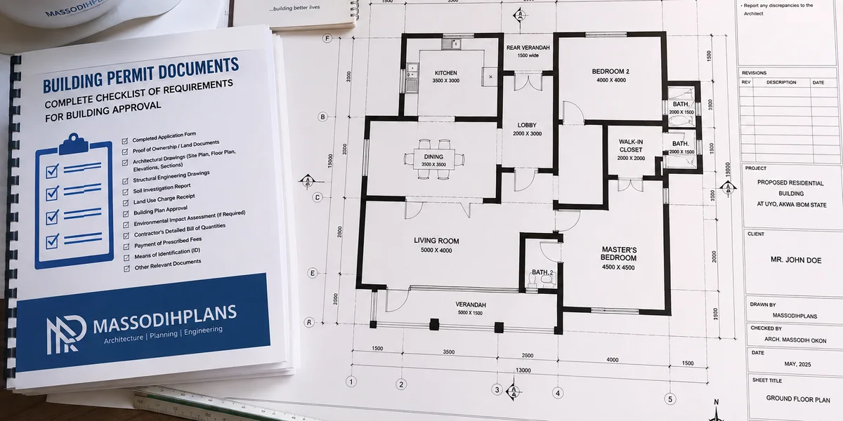
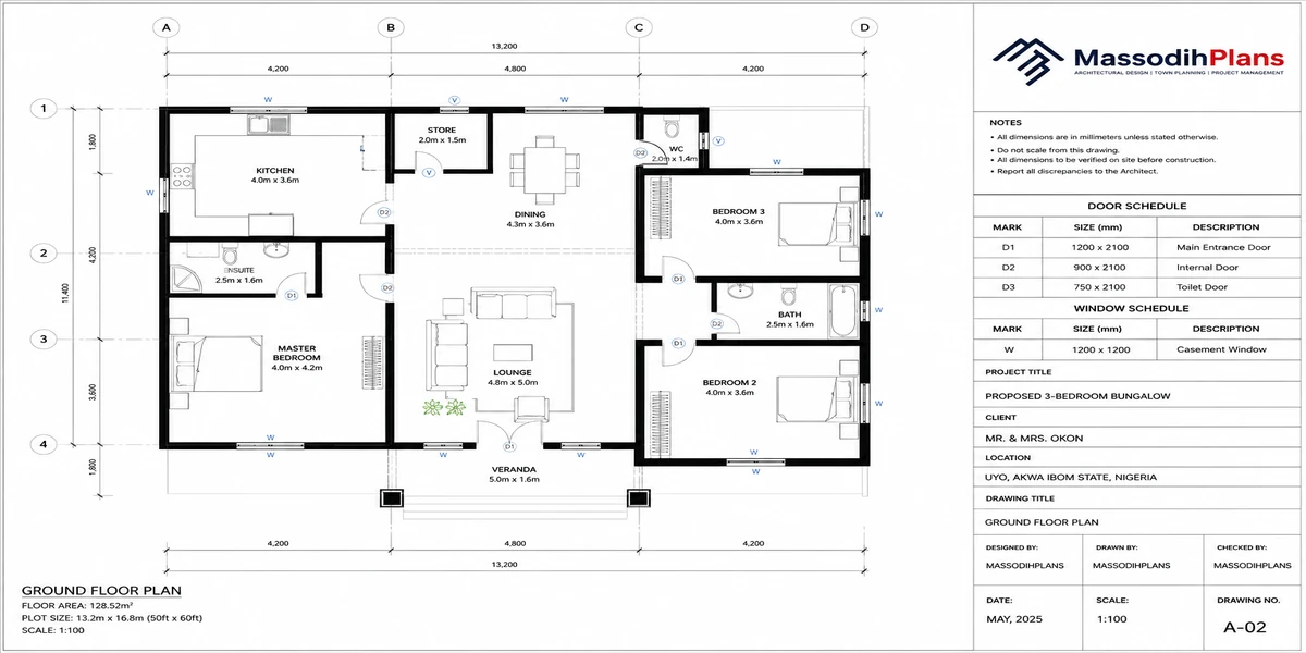
| Floor plans, approval submission | 1:100 | Standard for permits; whole house fits one sheet |
| Floor plans, working drawings | 1:50 | Shows door swings, stair treads, fittings, wall build-up |
| Roof plan | 1:100 | Shows slopes, ridges, gutters, outlets |
| Elevations (front, rear, sides) | 1:100 or 1:50 | 1:50 if you want openings and finishes readable |
| Sections | 1:50 or 1:100 | 1:50 shows levels, slab and roof build-up |
| Foundation and structural layouts | 1:50 or 1:100 | The engineer’s call; 1:50 for small footprints |
| Electrical and plumbing layouts | 1:100 (1:50 for crowded rooms) | Points and runs must not overlap |
| Staircase, wall sections, joinery | 1:20 | Shows how it is built |
| Small construction details | 1:10 or 1:5 | Shows junctions and fixings |
The Federal Housing Authority’s published guidance gives the same pattern. Its site plans are presented at 1:100 to 1:200 depending on the scope, while sections and elevations are drawn at 1:50 to 1:100. That matches my table, and it is a useful reference when you are not sure. Fha
My table is the professional norm, not the law. Each state, agency and estate publishes its own submission checklist. Get that checklist first, and if it names a scale, use that scale even if you prefer another. A correct drawing at the wrong scale can still be returned to you.
Now that you have the answer, let me explain what a scale actually is. Once you understand it, you will never need to memorise this table again.
What “1:100” Really Means (and Three Formulas That Replace Memorising)
A scale is a ratio between the length on paper and the length in the real building. At 1:100, one unit on paper stands for 100 of the same unit in reality. So 1 mm on paper is 100 mm on site, and 1 cm on paper is 100 cm, which is 1 m. That is why 1:100 is so convenient in metric: 1 cm on the drawing equals 1 metre on the ground.
Three formulas cover everything in this article:
Drawn length = Real length ÷ S
Real length = Drawn length × S
S = Real length ÷ Drawn length
where S is the second number in the scale (100 for 1:100).
Let us run a bedroom through them. A bedroom 3.6 m wide is 3,600 mm.
- At 1:100, it draws as 3,600 ÷ 100 = 36 mm.
- At 1:50, it draws as 3,600 ÷ 50 = 72 mm.
- At 1:200, it draws as 3,600 ÷ 200 = 18 mm.
The same room is drawn at three sizes and none of them is wrong, because each one is true to its own scale.
Large scale vs small scale: the confusion that trips students
People assume 1:200 is the “bigger” scale because the number is bigger. It is the opposite. A large-scale drawing has a small ratio number (1:20 or 1:50) and shows a small area in a lot of detail. A small-scale drawing has a big ratio number (1:500 or 1:1000) and shows a large area in little detail. If an examiner in a WAEC-style question or a university crit asks for “a larger scale,” go down the ratio, not up.
Area does not scale the way length does
This one catches people checking room sizes with a ruler. Lengths shrink by S, but areas shrink by S squared.
Real area (m²) = Drawn area (cm²) × S² ÷ 10,000
Worked example: the 3.6 m × 4.0 m bedroom is 14.4 m². At 1:100 it draws as 36 mm × 40 mm, which is 3.6 cm × 4.0 cm = 14.4 cm². So at 1:100, 1 cm² on paper equals 1 m² on site. At 1:50, 1 cm² equals 0.25 m². At 1:200, 1 cm² equals 4 m². Keep this in mind, because a plan drawn at the wrong scale will mislead you about area much faster than it misleads you about length.
With the basics settled, the natural next question is why 1:100 and 1:50 do most of the work and 1:200 does not.
Why 1:100 and 1:50 Carry Most Residential Drawings
It comes down to whether the things you need to show are still visible. A pen line is about 0.25 to 0.5 mm wide, and two lines closer than about 1 mm blur into one. So the smallest real gap a drawing can show is roughly 1 mm × S. At 1:100 that is 100 mm. At 1:200 it is 200 mm.
Here is how common house elements look at each scale. All figures are drawn size in millimetres.
| Real element | 1:20 | 1:50 | 1:100 | 1:200 | 1:500 |
|---|---|---|---|---|---|
| 225 mm external block wall | 11.25 | 4.5 | 2.25 | 1.125 | 0.45 |
| 150 mm internal block wall | 7.5 | 3.0 | 1.5 | 0.75 | 0.3 |
| 900 mm door leaf | 45 | 18 | 9 | 4.5 | 1.8 |
| 1,200 mm window | 60 | 24 | 12 | 6 | 2.4 |
| 250 mm stair tread | 12.5 | 5 | 2.5 | 1.25 | 0.5 |
| 3,600 mm bedroom width | 180 | 72 | 36 | 18 | 7.2 |
Read across the 225 mm wall row. At 1:100 the wall is 2.25 mm thick, enough for two clean lines with a hatch between them. And at 1:200 it is 1.125 mm, which is just a heavy line, so you cannot tell a wall from a thickened line. At 1:500 it is under half a millimetre, which is why 1:500 is a site scale and not a floor-plan scale.
The stair tread row shows why working drawings go to 1:50. At 1:100 a 250 mm tread draws as 2.5 mm, so twelve treads become a tiny comb. At 1:50 each tread is 5 mm and you can count steps and place a handrail. A door swing arc at 1:100 has a 9 mm radius, which is readable, but at 1:50 you can see whether the door actually clears the bed.
So 1:100 is good for “where is everything,” and 1:50 is good for “how is everything built.” That one rule explains why the approval set is at 1:100 and the builder’s set is at 1:50.
Never draw insulation, finishes, tile patterns or fixings at 1:100. If you feel the urge to add that level of detail, it belongs on a 1:20 or 1:10 detail sheet. A crowded 1:100 plan is harder to read, and a plan that is hard to read gets misread on site.
How to Choose a Scale With a Formula (Not a Guess)
Even with the table, a real question comes up on every project: which scale fits my plot on the paper I have? Most people try scales until something fits. You can calculate it instead.
First, allow about 120 mm on each axis of the sheet for the border, dimension strings and title block. Then:
S ≥ Real length ÷ (Sheet length − 120 mm) for each direction, and you take the larger answer.
After that, round up to the next standard scale (1:20, 1:50, 1:100, 1:200, 1:500, 1:1000).
Worked example 1: a full plot (15 m × 30 m) on A3
A3 is 420 × 297 mm. Usable length is 420 − 120 = 300 mm and usable width is 297 − 120 = 177 mm.
- Along the 30 m side: 30,000 ÷ 300 = 100
- Along the 15 m side: 15,000 ÷ 177 = 84.7
The larger number is 100, so 1:100 on A3 works, though only just. That tells you the plot fits snugly.
Worked example 2: the same plot on A4
A4 is 297 × 210 mm. Usable length is 177 mm and usable width is 90 mm.
- 30,000 ÷ 177 = 169.5
- 15,000 ÷ 90 = 166.7
The larger number is 169.5, and the next standard scale up is 1:200. So a full plot site plan fits on a single A4 at 1:200, which is handy for a quick sketch to send on WhatsApp.
Worked example 3: a house (11 m × 14 m) on A3, then on A2
On A3: 14,000 ÷ 300 = 46.7 and 11,000 ÷ 177 = 62.1. The larger is 62.1, which rounds up to 1:100. That means a 1:50 plan of this house will not fit A3.
On A2 (594 × 420 mm): 14,000 ÷ 474 = 29.5 and 11,000 ÷ 300 = 36.7. The larger is 36.7, which rounds up to 1:50. So an A2 sheet is the smallest that holds this house at 1:50.
Here is the same idea as a ready-made table. It assumes the standard allowance of 120 mm.
| Plot or house | Size | Scale | Drawn size | Smallest sheet |
|---|---|---|---|---|
| Half plot (about 50×50 ft) | 15 × 15 m | 1:200 | 75 × 75 mm | A4 |
| Half plot | 15 × 15 m | 1:100 | 150 × 150 mm | A3 |
| Half plot | 15 × 15 m | 1:50 | 300 × 300 mm | A2 |
| Full plot (about 50×100 ft) | 15 × 30 m | 1:200 | 75 × 150 mm | A4 |
| Full plot | 15 × 30 m | 1:100 | 150 × 300 mm | A3 (snug) |
| Full plot | 15 × 30 m | 1:50 | 300 × 600 mm | A1 |
| 600 m² plot | 20 × 30 m | 1:200 | 100 × 150 mm | A3 |
| 600 m² plot | 20 × 30 m | 1:100 | 200 × 300 mm | A2 |
| One-hectare estate block | 100 × 100 m | 1:1000 | 100 × 100 mm | A3 |
| One-hectare estate block | 100 × 100 m | 1:500 | 200 × 200 mm | A2 |
| 3-bed house footprint | 11 × 14 m | 1:100 | 110 × 140 mm | A3 |
| 3-bed house footprint | 11 × 14 m | 1:50 | 220 × 280 mm | A2 |
A quick note on the plot sizes, since many Nigerians still talk in feet. 1 ft = 0.3048 m, so a 50 ft × 100 ft plot is 15.24 m × 30.48 m, which is about 464.5 m². I round to 15 × 30 m in the table so the arithmetic stays visible. Always use your survey plan’s exact figures on the real drawing.
Small Plots: Where the Choice of Scale Changes the Design
All of this matters more when your land is small, and since this site exists to help people build well on small plots, let us talk about why.
On a half plot, you are fighting for centimetres. After front, side and rear setbacks, a 15 × 15 m plot often leaves a buildable area of roughly 9 × 9 m or less, depending on your authority’s rules. At 1:100, that buildable area is 90 mm × 90 mm on paper. You can see the shape of the house, but you cannot see whether the corridor is a comfortable 900 mm wide or a miserable 750 mm.
So here is the approach I recommend to clients and students working on small land:
- Design the layout at 1:50. Rough it out on tracing paper or on screen. At this scale, a 900 mm passage is 18 mm and you can feel whether it is tight.
- Check furniture by cut-out. Cut paper shapes at the same scale and slide them around the plan.
- Issue the approval set at 1:100, with setback dimensions written clearly on the site plan.
- Issue the builder’s set at 1:50, with the dimension strings that the site team will use.
Here are the cut-out sizes so you do not have to compute them:
| Item | Real size (mm) | At 1:50 (mm) | At 1:100 (mm) |
|---|---|---|---|
| Double bed (1.8 m wide) | 1,800 × 2,000 | 36 × 40 | 18 × 20 |
| Three-seater sofa | 2,100 × 900 | 42 × 18 | 21 × 9 |
| Six-seater dining table | 1,800 × 900 | 36 × 18 | 18 × 9 |
| Wardrobe depth | 600 | 12 | 6 |
| Minimum walking space | 900 | 18 | 9 |
| Car parking bay | 2,500 × 5,000 | 50 × 100 | 25 × 50 |
The last row of that table matters on small plots. A car bay at 1:100 is a 25 × 50 mm rectangle. If you cannot fit that rectangle inside the front setback area on your plan, the car will not fit on the ground either.
If your drawn passage between two furniture cut-outs is smaller than 18 mm at 1:50 (or 9 mm at 1:100), the real gap is under 900 mm. Redesign now. Moving a wall on paper costs nothing, and moving a block wall costs a lot.
Next, let me tell you about the thing that goes wrong most often in practice, which has nothing to do with choosing the scale.
The Print-Scale Trap: Why a Correct Plan Becomes a Wrong One
A drawing’s scale is correct only at the paper size it was drawn for. Change the paper size and the printed scale changes, whatever the title block says.
Paper sizes in the A-series go down by a linear ratio of about 0.707 at each step. So:
Effective scale = Labelled scale ÷ r, where r is the linear reduction ratio.
| Drawn on → Printed on | r | A “1:100” drawing becomes |
|---|---|---|
| A1 → A2 | 0.707 | 1:141 |
| A1 → A3 | 0.5 | 1:200 |
| A1 → A4 | 0.354 | 1:283 |
| A2 → A3 | 0.707 | 1:141 |
| A2 → A4 | 0.5 | 1:200 |
| A3 → A4 | 0.707 | 1:141 |
A 1:50 drawing on A1 printed on A3 becomes 1:100, which is a milder version of the same problem.
Now work the example from the start of this article. The bedroom is 3.6 m wide, drawn at 1:100 on A1, so it is 36 mm on the original. The client prints on A3 (r = 0.5), so it is now 18 mm on paper. The contractor reads 18 mm with a 1:100 ruler: 18 × 100 = 1,800 mm. The real width is 3,600 mm. His reading is 50% short.
Reading error (%) = (S_labelled − S_effective) ÷ S_effective × 100
= (100 − 200) ÷ 200 × 100 = −50%.
It gets worse in the quieter cases. If the print driver shrinks to 87% to “fit,” the effective scale is 100 ÷ 0.87 ≈ 1:115, and you are 13% short everywhere. A 6 m setback reads as 5.2 m. Nobody notices until the building line is checked.
Three defences, and I use all of them:
- Add a graphic scale bar to every drawing. A bar scales with the print, so it keeps telling the truth when the ratio in the title block does not.
- Print at 100% or “actual size,” never “fit to page,” and tell your printer the sheet size explicitly.
- Build from figured dimensions, not from a ruler. Good drawings carry a note: “Do not scale from drawing. Use figured dimensions only.” If you are the builder and a dimension is missing, ask. Do not measure the paper.
A photo of a plan taken on a phone and sent over WhatsApp is not a scaled drawing, even if it was one before. Angles and lens distortion change every dimension. Send the PDF and make sure it was exported at actual size.
The Ten-Second Ruler Test: Check Any Plan’s Scale
This is the tool I promised, and you can use it on any plan someone hands you. It rests on one fact: some building elements have almost standard sizes. Use them as a reference, then confirm against a written dimension.
S = Real size ÷ Measured size on paper
| Reference | Typical real size | If it measures this on paper… | …the scale is |
|---|---|---|---|
| Internal door leaf | 900 mm | 18 mm | 1:50 |
| Internal door leaf | 900 mm | 9 mm | 1:100 |
| Internal door leaf | 900 mm | 4.5 mm | 1:200 |
| External block wall | 225 mm | 4.5 mm | 1:50 |
| External block wall | 225 mm | 2.25 mm | 1:100 |
| Car parking bay width | 2,500 mm | 25 mm | 1:100 |
Then confirm with a written dimension. If a dimension string says 3,600 and you measure 36 mm, the scale is 1:100. If it says 3,600 and you measure 18 mm, then the sheet has been shrunk and you are not holding a 1:100 drawing, regardless of what the title block says.
Do this every time you receive a plan, whether it is from an architect, a friend, an online plan seller or a diaspora relative. It takes less time than reading this paragraph, and it saves the kind of argument that happens after the DPC is poured.
Metric vs Imperial: The 4% Error Nobody Warns You About
Nigerian practice is metric, but plots are often described in feet, older drawings are in feet and inches, and many diaspora clients bring plans from the United States. That is where the quiet mistake lives.
An imperial scale of 1/4″ = 1′-0″ is exactly 1:48, not 1:50. And 1/8″ = 1′-0″ is exactly 1:96, not 1:100. They look almost identical, but the difference is 4.17%.
Run the numbers. A 15 m wall drawn at 1:48 is 15,000 ÷ 48 = 312.5 mm on paper. If someone reads it with a 1:50 ruler, he gets 312.5 × 50 = 15,625 mm. That is 625 mm of error on one wall, which is wider than a door. On a 6 m front setback the error is 6,000 × 0.0417 = 250 mm, enough to put your building line over the limit on paper and on the ground.
Here is a conversion table for imperial scales you may meet:
| Imperial scale | Ratio |
|---|---|
| 1/16″ = 1′-0″ | 1:192 |
| 1/8″ = 1′-0″ | 1:96 |
| 3/16″ = 1′-0″ | 1:64 |
| 1/4″ = 1′-0″ | 1:48 |
| 3/8″ = 1′-0″ | 1:32 |
| 1/2″ = 1′-0″ | 1:24 |
| 3/4″ = 1′-0″ | 1:16 |
| 1″ = 1′-0″ | 1:12 |
| 1″ = 20′-0″ (US site plans) | 1:240 |
The formula is simple: ratio = 12 ÷ (inches per foot). So 1/4″ per foot is 12 ÷ 0.25 = 48.
My advice: do not mix systems on one drawing. If you receive a plan from abroad in feet and inches, have it re-issued in millimetres at a metric scale before it goes to a Nigerian planning office. Converting by eye is how 4% errors enter a set of drawings.
Drawing to Scale in AutoCAD and Other Software
Software removes the ruler but adds a new way to get the scale wrong. Students and junior draftsmen ask me this more than anything else, so here is the reliable method.
Draw everything at full size (1:1) in model space, in millimetres. The scale is set only when you lay the drawing out for printing.
- In a layout viewport, the viewport scale is 1 ÷ S. For 1:100 that is 0.01 (written 0.01XP), for 1:50 it is 0.02 and for 1:200 it is 0.005.
- Text and dimensions must be sized so they look right when printed: Model-space text height = Plotted text height × S.
| Plotted text height | At 1:50 | At 1:100 | At 1:200 |
|---|---|---|---|
| 2.5 mm | 125 mm | 250 mm | 500 mm |
| 3.5 mm | 175 mm | 350 mm | 700 mm |
- Set the dimension scale factor equal to S. If your arrows and text look microscopic on the sheet, this is nearly always the reason.
- Plot at 1:1 (actual size) from the layout, because the viewport already carries the scale. Export PDFs the same way.
If you are learning, my strongest advice is not to draw in metres. Some beginners draw a 3.6 m room as “3.6” and then wonder why text and hatches behave strangely. Millimetres keep every standard dimension a whole number, and it is the convention in most offices.
What Your Drawing Sheet Must Carry
Choosing the scale is half the job. The other half is making sure the scale can be checked by whoever receives the drawing. Every sheet should have:
- The scale written under each drawing, not only in the title block, because one sheet often carries two scales (for example 1:100 for a plan and 1:20 for a staircase detail).
- A graphic scale bar (0–1–2–5 m for 1:100).
- A north point on every plan.
- The original sheet size in the title block (“A1 original”).
- The statement “Do not scale from drawing” next to the figured dimensions.
- The drawing’s revision date, so a later print does not get confused with an earlier one.
“NOT TO SCALE” (NTS) is a legitimate label for diagrams and sketches. If you mark a drawing NTS, nobody should be building or measuring from it. Do not put it on any sheet the contractor will use for setting out.
Scale Around the World: Same Idea, Different Habits
Whether you are drawing in Port Harcourt, Houston or Hamburg, the logic of scale is identical, and the formulas in this article work in any country. What changes is the habit, and it matters if you are a diaspora client commissioning a house back home, or a Nigerian designer sending drawings abroad. These are typical practices, not legal rules, so always confirm with the local authority.
| Region | Typical practice |
|---|---|
| Nigeria | Metric. Floor plans 1:100 (1:50 for working drawings), site plans 1:100–1:200, with state-specific variations |
| United Kingdom | Metric. Plans and elevations at 1:50 or 1:100, block plan at 1:500 or 1:200, location plan at 1:1250 or 1:2500 |
| United States | Imperial. Plans at 1/4″ = 1′-0″ (1:48) for houses, 1/8″ for larger buildings, site plans often 1″ = 20′ (1:240) |
| Canada | A mix of metric and imperial depending on the province, firm and project |
| Germany, Switzerland, Luxembourg, Austria | Metric. Floor plans commonly 1:100 for permits, site plans commonly 1:500 |
| Australia | Metric. Floor plans commonly 1:100, site plans 1:200 or 1:500 |
| UAE, Qatar, Singapore, Iceland | Metric. Permit drawings commonly at 1:100, with site plans at 1:200 or 1:500 |
If you live abroad and have a designer there produce your Nigerian house plan, ask them for a metric set in millimetres at 1:100 and 1:50 from the start. It saves a conversion step and a 4.17% risk. And if you are a Nigerian student sending a portfolio abroad, convert your sheets to the host country’s usual format, because a reviewer who cannot read your scale quickly will not give you the benefit of the doubt.
Eight Scale Mistakes I See Most Often (and the Fix for Each)
- Drawing a house at 1:200 to “save paper.” The walls become single lines and the plan is useless for construction. Fix: 1:100 minimum for a floor plan.
- Printing “fit to page.” The title block lies. Fix: print at 100% and check the scale bar.
- Measuring from the paper instead of reading figured dimensions. Fix: use the written dimensions; ask the designer if one is missing.
- Mixing 1:48 and 1:50 in one drawing set. Fix: pick metric and stay there.
- One scale for the whole sheet when two are needed. Fix: label each view and give each its own scale bar.
- Text too small on the sheet. Fix: model-space text height = plotted height × S.
- Drawing the plot at 1:100 and never checking furniture at 1:50. Fix: test the layout at 1:50 or with cut-outs before finalising.
- Photographing a plan and treating the photo as a drawing. Fix: send the PDF, exported at actual size.
Your Pre-Submission Scale Checklist
Before you print or send a set, go through this:
- Did I confirm the scale my approval authority requires?
- Is every drawing labelled with its own scale?
- Does each sheet have a graphic scale bar?
- Did I print at 100% and then measure the scale bar with a ruler?
- Do the figured dimensions agree with the drawn lengths (the door test, at least once per sheet)?
- Is the sheet size stated in the title block?
- Are the setbacks dimensioned, not just drawn?
- Is the set entirely metric?
- Has the site team been told to use dimensions, not rulers?
Frequently Asked Questions
What scale should I use for a house plan in Nigeria?
Use 1:100 for approval floor plans, elevations and sections, 1:50 for working drawings and small-plot design, and 1:200 for the site plan, unless your approval authority specifies otherwise.
Is 1:50 or 1:100 better for a house plan?
Neither is better in general. 1:100 is better for showing the whole house on one sheet and for permit submissions. 1:50 is better for construction detail and tight layouts. Most projects use both.
What scale should a site plan be drawn at?
Usually 1:200 for a standard residential plot, or 1:100 when the plot is small enough to fit. Larger layouts such as estates use 1:500 or 1:1000. Federal Housing guidance mentions 1:100–1:200 for site plans.
What does the scale 1:100 mean in simple words?
It means the real building is 100 times bigger than the drawing. 1 cm on paper is 1 m on the ground.
How do I convert 1:100 to feet and inches?
The nearest imperial scale is 1/8″ = 1′-0″, which is 1:96. They are close, but not equal, and a 4.17% difference is enough to cause a setback problem.
What paper size do I need for 1:100?
It depends on the size of the drawing. Use the formula S ≥ Real length ÷ (Sheet length − 120 mm). A 11 × 14 m house at 1:100 fits an A3 sheet.
Can I enlarge a drawing by photocopying?
Yes, but the scale changes with the enlargement. Enlarging a 1:100 drawing by 200% gives 1:50, and you must check the scale bar afterwards, because most machines are not exact.
What does “Not to Scale” mean on a plan?
It means the drawing is a diagram or sketch whose proportions cannot be trusted. Nothing should be built or measured from it.
What scale do WAEC and school technical-drawing questions use?
Questions state the scale, and you must follow it. Plan reproduction questions commonly use 1:100, and some detail questions use 1:50 or 1:20. Read the instruction first and write the scale under your drawing.
Can I change a CAD drawing’s scale later?
If it was drawn at 1:1 in model space, yes. Change the viewport scale, then adjust text and dimension scale factors to match. If it was drawn at a reduced size, you will have to scale the whole drawing, which is a good reason to draw at 1:1 from the start.
Is it safe to measure from a printed plan?
Only if you have verified the printed scale against the scale bar, and even then you should prefer the written dimensions. Paper stretches, printers adjust, and photocopies drift.
Conclusion
The best scale for a house plan in Nigeria is the one that lets the person reading the drawing see what they need to see, and trust what they measure. For most homes that means 1:100 for the approval set, 1:50 for the builder’s set, 1:200 for the site plan, and 1:20 or finer for details. On a small plot, add one more habit: test the layout at 1:50 before you finish it, because the difference between a comfortable house and a cramped one is often a few centimetres.
The second half of the lesson matters just as much. A scale is only a promise, and printing, photocopying and photographing all break it. Keep a scale bar on every sheet, build from figured dimensions, and use the door test on any plan you did not draw yourself. If you do that, you will avoid the mistakes that waste the most money on small plots.
If you are drawing your own plan, visit Plan School to learn how to set out a drawing set properly. And if you want a ready design that is already dimensioned for Nigerian small plots, browse the Plans Library. If you want us to prepare a metric drawing set or review one you already have, see our Services page, or go back to the Homepage for more building and planning guides.
- How to Draw Walls Correctly in Floor Plans: Thickness & Scale
- Best Way to Learn AutoCAD for House Plans: The 8-Week Plan Built Around One Real Plot
- How to Calculate Room Sizes Correctly (Formulas + Examples)
- Smart Nigerian Duplex Plans That Maximize Small Land (50×50, 50×75, 50×100 ft)
- 3 Bedroom House Plan With Dimensions in Meters
Author
Massodih Okon is a Nigerian built-environment professional with academic and professional experience in urban and regional planning, geography, architectural design, Landscape Design, GIS and land development.
He holds a Master’s degree in Urban and Regional Planning from the University of Uyo and a first degree in Geography and Regional Planning.
Through MassodihPlans, he publishes practical guides on Nigerian house plans, building design, physical planning, site planning, development approval and residential construction. Read the full author profile →