How to Draw Walls Correctly in Floor Plans: Thickness & Scale
To draw walls correctly in a floor plan, draw every wall as two parallel lines set apart by its real finished thickness. In Nigeria that is about 250 mm for a plastered 225 mm block wall and about 175 mm for a plastered 150 mm partition. Draw them to scale in your heaviest line weight, join every corner so no line gaps or crosses, and measure each room from wall face to wall face, not from line to line. Do those four things and your drawing tells the truth. Miss one and the rooms on paper are not the rooms you will get on site.
I am saying this with a calculator in mind, not as a lecture. Picture three bedrooms side by side, each sketched 3.60 m wide with single lines. Built on site, those rooms come out at about 3.39 m, 3.43 m and 3.39 m, because nobody paid for the thickness of the walls. That is 18 to 21 cm gone from every room, enough to squeeze a 1.8 m bed and two bedside tables against the wall. On a 15 m wide plot with setbacks to respect, the same mistake can decide whether the house fits at all.
So stay with me to the end. Below you will find the thickness tables for Nigeria and eleven other countries, the formulas that tell you exactly where each wall goes, a step-by-step method for hand drawing and CAD, and a thirty-second test that finds gaps in your walls. Near the bottom is the pipe problem that sinks more bathroom walls than any other, and I almost never see it explained.
Whether you are a student drawing your first plan, a homeowner checking what a draughtsman handed you, or a self-builder squeezing a family home onto a small plot, treat this as me talking you through it across a table. First, what a wall actually is on paper.
What a Wall Really Is on a Floor Plan
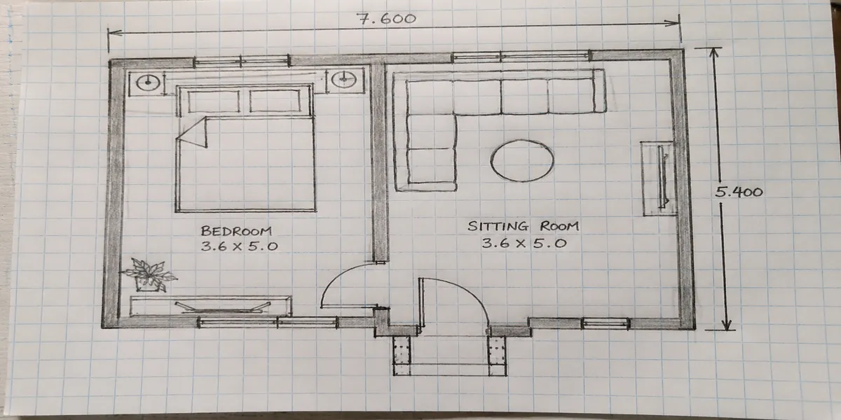
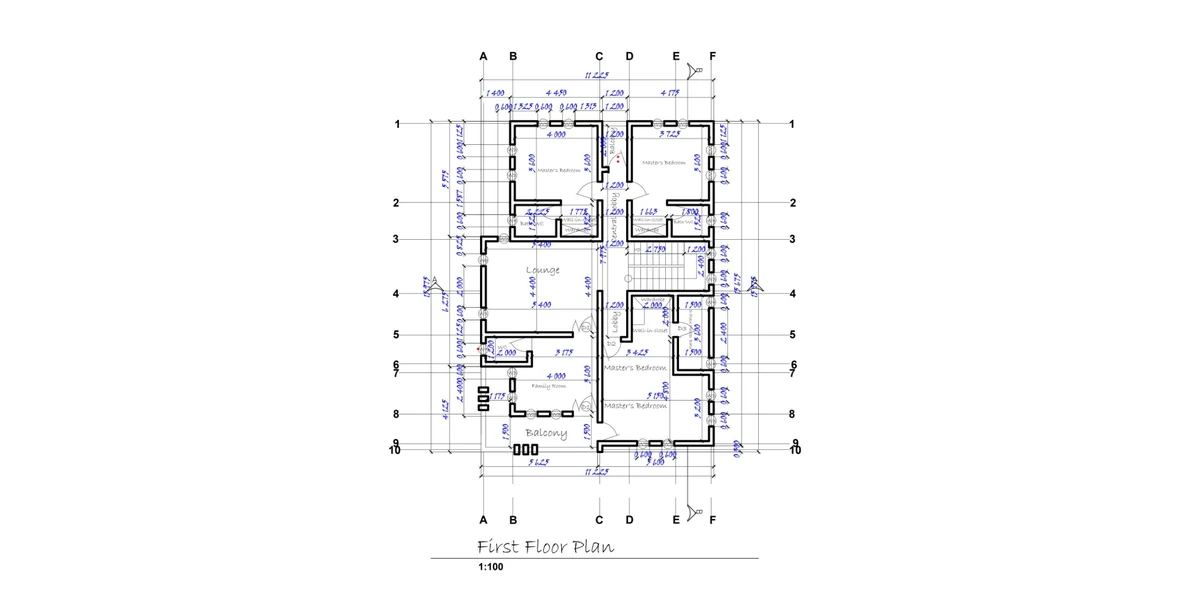
A floor plan is not a picture of your house from above. It is a slice. Imagine a giant horizontal knife cutting through the building at about 1.2 m above the floor (4 ft in the US), then you lift off the top and look down. Everything the knife passes through is a cut element, and cut elements get the heaviest lines. Walls, columns, and the frames of doors and windows are all cut. That is why a wall shows up as a thick, bold shape, and why a wall that was only a single line in your head has to become two lines on paper.
Things below the knife, such as a kitchen counter or a basin, are drawn lighter. Things above it, such as a high window or a beam, are drawn dashed. This one idea explains most of the “why does my plan look wrong” questions, so keep it in your pocket.
Now that you know what you are drawing, you have to settle how thick it is before you put pencil or cursor to anything.
Step Zero: Decide the Wall Thickness Before You Draw
The most common reason a drawn plan and a built house disagree is that nobody decided, in writing, what “a 9-inch wall” means. Is it 225 mm of block only, or 250 mm with plaster? Here is the formula I want you to carry:
t = b + 2p
where t is the finished wall thickness, b is the block (or brick, or stud) thickness, and p is the plaster or finish thickness on one face.
For Nigerian sandcrete blocks, the nominal block sizes are 450 × 225 × 225 mm and 450 × 225 × 150 mm. With a typical 12.5 mm plaster coat on each face, you get this:
| Wall type | Block thickness (b) | Plaster each face (p) | Finished thickness (t) | Typical use |
|---|---|---|---|---|
| 225 mm (9 in) | 225 | 12.5 | 250 mm | External walls, boundary walls |
| 150 mm (6 in) | 150 | 12.5 | 175 mm | Internal partitions |
| 100 mm (4 in) | 100 | 12.5 | 125 mm | Light enclosures, non-structural only, confirm with your engineer |
Plaster in real life is often thicker than the textbook number, so test your own site:
| Plaster per face (p) | 225 block finishes at | 150 block finishes at |
|---|---|---|
| 12.5 mm | 250 mm | 175 mm |
| 15 mm | 255 mm | 180 mm |
| 20 mm | 265 mm | 190 mm |
Those 15 mm of difference per wall add up fast when you stack walls across a room run, which is the next thing we will do. For now, pick your p and stick with it.
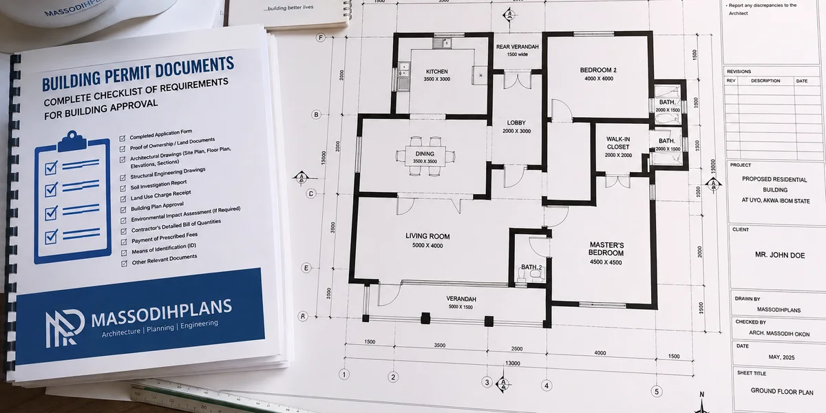
For design and approval drawings, draw the finished thickness (250 and 175) and write the block size in the wall legend. Room sizes then match what a client can actually measure with a tape after plastering.
If you work outside Nigeria, the same formula holds. Only the numbers change.
Wall Thickness Around the World
A wall is a wall in Houston, Hamburg, Dubai and Singapore. Only the build-up differs, so the process is identical and you simply change b and p. These are typical ranges, not code values. Your local building code and structural engineer always have the last word.
| Country | Typical external wall (finished) | Typical internal partition (finished) |
|---|---|---|
| Nigeria | About 250 mm (225 block + plaster) | About 175 mm (150 block + plaster) |
| United States | About 170 to 205 mm (2×6 framing, board, sheathing, cladding) | About 114 mm (2×4 stud + ½ in drywall both sides) |
| Canada | 2×6 framing is common; about 200 to 300 mm with exterior insulation | About 114 to 140 mm (2×4 or 2×6 stud + drywall) |
| United Kingdom | About 300 to 350 mm (brick, cavity, block, plaster) | About 100 to 125 mm (block or stud + board) |
| Germany | About 365 to 480 mm (monolithic masonry, often with insulation) | 115 or 175 mm masonry, plus plaster |
| Switzerland and Luxembourg | About 300 to 450 mm (high-insulation walls) | About 100 to 175 mm |
| Iceland | About 250 to 400 mm (insulated concrete) | About 100 to 200 mm |
| United Arab Emirates and Qatar | About 200 to 250 mm (block + plaster) | About 100 to 175 mm |
| Australia | About 250 mm (brick veneer: 110 brick + 40 cavity + 90 frame + 10 board) | About 110 mm (90 stud + 10 mm board each side) |
| Singapore | About 150 to 200 mm | About 100 to 125 mm |
Two things jump out. First, the thicker the external wall, the bigger the penalty on a small plot, and cold-country walls cost far more floor area than Nigerian ones. Second, drawing conventions differ. US plans often dimension to the face of the stud, while UK and European plans often dimension to the structural or finished face. A single note on your sheet ends arguments before they start. Which brings us to the decision that quietly moves your rooms more than anything else.
Centerline or Face? The Choice That Moves Your Rooms
You can describe a wall’s position in two ways. You can say where its centerline is, or where its faces are. Neither is wrong. Mixing them without telling anyone is what ruins houses.
| Method | What the dimension runs to | Best for | Risk |
|---|---|---|---|
| Centerline | The middle of the wall | Structural grids, column positions, foundation setting out | Rooms are smaller than the dimension suggests |
| Face (clear) | The finished inner surface | Designing rooms, furniture fit, selling the plan to a client | Needs extra arithmetic for structure |
Here are the three formulas that connect them. Memorize these and you can convert anything.
1. Clear dimension from centerline spacing:
C = S − (t₁ + t₂) ÷ 2
where S is the centerline-to-centerline spacing and t₁, t₂ are the thicknesses of the two walls.
2. Centerline spacing needed for a wanted clear size:
S = C + (t₁ + t₂) ÷ 2
3. Overall external length of n rooms in a row:
E = Σ clear widths + (n − 1) × t_internal + 2 × t_external
Worked Example 1: Three Bedrooms in a Row
You want three bedrooms, each 3.60 m clear, with finished walls of 250 mm outside and 175 mm inside.
E = (3 × 3.60) + (2 × 0.175) + (2 × 0.25)
E = 10.80 + 0.35 + 0.50 = 11.65 m
Now see what the single-line sketch does. If someone draws centerlines 3.60 m apart, the overall width is only 10.80 + 0.25 = 11.05 m, and the real clear sizes become:
| Room | Calculation | Clear width | Lost against 3.60 m |
|---|---|---|---|
| Bedroom 1 (outer) | 3.60 − 0.125 − 0.0875 | 3.39 m | 21 cm |
| Bedroom 2 (middle) | 3.60 − 0.0875 − 0.0875 | 3.43 m | 17.5 cm |
| Bedroom 3 (outer) | 3.60 − 0.0875 − 0.125 | 3.39 m | 21 cm |
Check the bed. A 1.8 m bed plus two 0.45 m bedside tables takes 2.70 m. In a 3.60 m room you keep 0.90 m of walking space. In the sketch room of 3.39 m you keep 0.69 m, and once a wardrobe door swings open, that number matters.
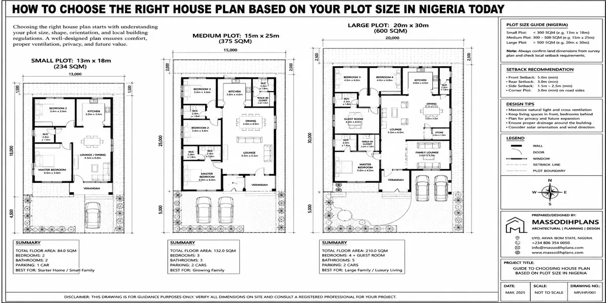
Does It Fit Your Plot?
The same arithmetic, turned around, tells you the biggest equal rooms your plot can hold. If B is the building width available after side setbacks:
c = (B − 2·t_e − (n − 1)·t_i) ÷ n
Take a 15 m wide plot (a standard 50 ft frontage) with three equal rooms. Setbacks below are illustrative, so confirm yours with your planning authority.
| Side setback each side | Building width B | Max clear room width (3 rooms) |
|---|---|---|
| 1.0 m | 13.0 m | 4.05 m |
| 1.5 m | 12.0 m | 3.72 m |
| 2.0 m | 11.0 m | 3.38 m |
| 3.0 m | 9.0 m | 2.72 m |
Three 3.60 m rooms need 11.65 m, so on a 15 m plot your side setbacks can be at most (15 − 11.65) ÷ 2 = 1.675 m. Anything bigger and one bedroom has to go, or the rooms have to shrink. That calculation, done in a minute before you draw, saves weeks of redrawing.
Write on every plan, in plain words, which method your dimensions use. Something like: “All room dimensions are clear internal sizes between finished wall faces. Grid dimensions are to wall centerlines.” One sentence on the sheet prevents most arguments on site.
With the numbers settled, you need to put them on paper at the right size.
Scale and Line Weights: Making Thickness Visible
On paper, a wall’s thickness is its real thickness divided by the scale number:
Paper thickness = real thickness ÷ scale denominator
| Real finished thickness | At 1:50 | At 1:100 | At 1:200 |
|---|---|---|---|
| 250 mm | 5.0 mm | 2.5 mm | 1.25 mm |
| 175 mm | 3.5 mm | 1.75 mm | 0.88 mm |
| 125 mm | 2.5 mm | 1.25 mm | 0.63 mm |
If you work in feet and inches, the common 1/4 in = 1 ft scale is 1:48, and a 9.8 in finished wall comes out at about 0.2 in on paper.
The sheet size tells you which scale you can use. An A3 sheet is 420 × 297 mm, so at 1:50 it can hold a plan up to 21 m × 14.85 m, and at 1:100 up to 42 m × 29.7 m. Our 11.65 m wide house at 1:50 needs 233 mm of width, which sits comfortably on A3 with space for dimensions and a title block. Use 1:50 for building plans whenever it fits, because it lets you see a 175 mm partition as a real 3.5 mm line.
Line weights are how the eye reads the drawing. Walls get the heaviest line because they are cut. Here is a typical hierarchy, though your office or school may set its own:
| Element | Typical pen weight |
|---|---|
| Cut walls and columns | 0.50 to 0.70 mm |
| Door and window symbols | 0.25 to 0.35 mm |
| Furniture and fixtures | 0.13 to 0.25 mm |
| Dimension lines and text | 0.13 to 0.18 mm |
| Hidden (dashed) lines | 0.18 to 0.25 mm |
One warning for CAD users. Draw at full size, 1:1 in millimetres, and set the scale only when you print or in your layout. A wall drawn “to scale” inside the model is a wall that will betray you the moment someone changes the sheet size.
How to Draw Walls Step by Step
There are two good ways to draw walls. Which one you use depends on the stage of your project.
Method A: Rooms First (the Negative-Space Method)
This is my favourite for small plots, because the rooms you promised the client stay exactly the size you promised. The idea is simple: draw the clear room sizes, and the walls are whatever space is left between them. A drafting handout hosted on Berkeley’s website teaches beginners the same order, drawing the inside lines first, then adding wall thickness outward, then adding doors and windows. berkeley
Here are the wall positions along the width for Example 1, measured from the outside face of the left wall. You can draw straight from this table:
| Element | From (m) | To (m) | Size |
|---|---|---|---|
| External wall (left) | 0.000 | 0.250 | 250 mm |
| Bedroom 1, clear | 0.250 | 3.850 | 3.60 m |
| Partition | 3.850 | 4.025 | 175 mm |
| Bedroom 2, clear | 4.025 | 7.625 | 3.60 m |
| Partition | 7.625 | 7.800 | 175 mm |
| Bedroom 3, clear | 7.800 | 11.400 | 3.60 m |
| External wall (right) | 11.400 | 11.650 | 250 mm |
In AutoCAD, the sequence runs like this:
- Set units to millimetres with UNITS, and draw at 1:1.
- Use RECTANG to draw each room as a clear rectangle at the coordinates above.
- Use OFFSET with a distance of 250 to push the outer boundary outward and create the external wall edge.
- Use HATCH, pick an internal point in the gap between rooms and the outer line, and fill it solid. Because the rooms and the outer boundary are all closed, one click fills the whole wall network.
- Move the wall layer to your heaviest line weight.
Notice what happened. You never calculated a single wall position, and no room can lose a centimetre.
Method B: Grid First (the Centerline Method)
You use this for working drawings when the engineer’s column grid rules the plan.
- Draw the structural grid on centerlines, on its own layer, with a light dash-dot line.
- Run a polyline along the centerlines for each wall.
- Offset each polyline by half the thickness on both sides. Offset 125 mm each way for a 250 mm wall, and 87.5 mm each way for a 175 mm wall.
- Clean every corner with FILLET at radius 0, and every T-junction with TRIM, so lines meet exactly.
- Join the wall pieces with PEDIT where you want one continuous outline, and hatch the fill.
Beginners sometimes prefer MLINE. Create a style with MLSTYLE with two elements at plus and minus half the thickness, draw with Justification set to Zero, and clean junctions with MLEDIT. It works, and it is a good way to learn, but most offices move to polylines and offsets as they get faster.
In Revit and ArchiCAD
Both programs ask you where the wall’s “location line” sits. In Revit the options include Wall Centerline, Core Centerline, and Finish Face Exterior or Interior. If you are designing by clear room sizes, set the location line to a finish face, so your rooms stay true. If you are working to a structural grid, use a centerline. Also, if your walls suddenly look too thick or too thin, check the view’s cut plane height, since the cut plane controls what the program slices through (commonly 1.2 m above the floor).
By Hand at 1:50
- Draw a faint grid of centerlines with a 2H pencil.
- Cut two small card gauges, one 5.0 mm wide for 250 mm walls and one 3.5 mm wide for 175 mm walls.
- Run the gauge along each centerline and mark both edges every 50 mm, then draw the edges with a parallel rule.
- Close corners with a set square, then fill the walls solid with a marker once the lines are right.
- Use a heavier pencil only after you have checked every dimension, because erasing a bold wall line wrecks the paper.
Once the walls are in, the real work begins at the places where walls meet other things.
Corners, Junctions and Columns
Corners look trivial and cause a surprising share of errors. In your drawing, an L-corner, a T-junction and a cross-junction should all read as one clean shape with no line running through the middle of the joint. In CAD, a quick check is the OVERKILL command, which deletes duplicate overlapping lines, and ORTHO or polar tracking, which keeps walls truly at 90°. A wall that is 0.3° off is invisible on screen and shows up later as a room whose two diagonals disagree.
Columns deserve their own paragraph, because Nigerian reinforced concrete frames use them everywhere. A typical column is 225 × 225 mm, which sits flush inside a 225 mm external wall, so both faces line up and nothing sticks out. Inside a 175 mm finished partition, though, the column is wider than the wall, and it will bulge into the room by 75 mm in total.
Decide which side of the partition gets the column bulge, and draw it that way. I like to keep the bedroom face flat and let the corridor side take the extra 75 mm, because a bulge in a corridor costs far less than one behind a bed or wardrobe.
Doors and Windows in Walls
Openings are cut out of the wall, never pasted over it. In a drawing, you break the wall lines where the opening sits and then draw the frame.
- Doors: draw the opening with two short lines at the edges, then the door leaf and its swing arc, so everyone can see which way it opens.
- Windows: show the opening in the wall thickness with thin lines running through it, usually three thin lines across the wall.
- Typical sizes in Nigerian practice: internal doors 0.9 m wide (0.75 to 0.8 m for small bathrooms), external doors 1.0 m or wider, and doors 2.1 m high.
- Keep about 100 to 150 mm between a door frame and the nearest corner so the leaf can open flat against the wall.
Every opening also reduces your block count. We will see how in a moment, after a problem that sits inside the walls themselves.
The Pipe Problem Nobody Draws
A common 110 mm soil pipe measures about 125 mm across its socket. If it is to sit inside a wall with 25 mm of cover on each side, the finished wall must be at least:
125 + 25 + 25 = 175 mm
That is exactly the finished thickness of a plastered 150 mm partition, which leaves zero tolerance. A mason who chases the block, and a plasterer who cannot get cover over the pipe, will give you a cracked, weak wall behind your toilet.
The fix is to choose, at drawing stage, one of two things. Either draw the wet wall as a 225 mm block wall (250 mm finished), or draw a dedicated duct beside the wall, at least 300 mm wide and clearly labelled. Do not leave it to the site. If the pipe is not on the drawing, it will be improvised, and improvisation is how bathrooms end up with leaking walls.
Pipes are one reason walls surprise you after the drawing. Setbacks are the other, and that one can stop your whole project.
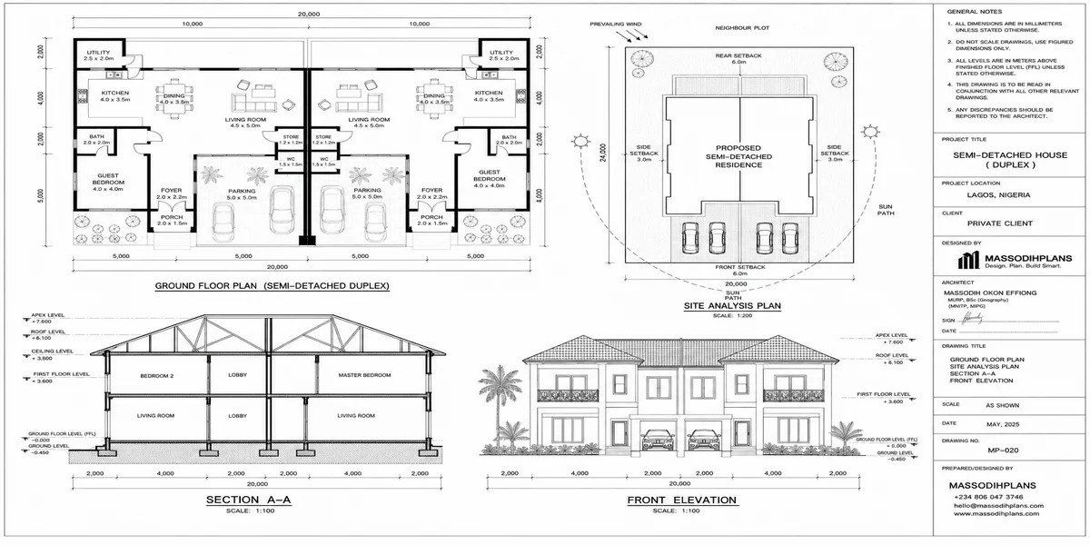
Walls and Setbacks: Where Approval Officers Look
Planning authorities measure setbacks to the building, which usually means the outer face of the wall. Some authorities also count the foundation, the eaves, or both, so ask yours which applies. Here is the formula for where to put the centerline of a wall that sits on the setback limit:
D_CL = S_b + t_e ÷ 2
With a 1.5 m setback and a 250 mm external wall, the centerline sits at 1.5 + 0.125 = 1.625 m from the boundary. If you draw the centerline at 1.5 m, the wall face lands at 1.375 m. That is 125 mm inside the forbidden strip, and a plan rejected for 125 mm is the kind of rejection that hurts because the fix means redrawing the whole width.
Plot coverage depends on this accuracy as well:
Coverage (%) = footprint area ÷ plot area × 100
For our 11.65 × 9.25 m footprint (107.76 m²) on a 15.24 × 30.48 m plot (464.5 m²), coverage is 107.76 ÷ 464.5 × 100 = 23.2%. Always compute the footprint from outer wall faces, not from centerlines.
How Much Floor Do Your Walls Eat?
Walls are not free. They cost floor area, and on a small plot you should know how much. Use this:
Wall ratio R = Σ(wall length × thickness) ÷ footprint area
For our example house, the external centerline perimeter is 2 × (11.40 + 9.00) = 40.8 m, and we assume 38 m of internal partitions:
- External: 40.8 × 0.25 = 10.20 m²
- Internal: 38 × 0.175 = 6.65 m²
- Total wall area: 16.85 m²
- R = 16.85 ÷ 107.76 = 15.6%
- Usable floor: 107.76 − 16.85 = 90.91 m²
Now see what happens if someone builds every partition from 225 mm blocks (finished 250) “to be safe”:
Internal wall area = 38 × 0.25 = 9.50 m², which is 2.85 m² more lost, roughly the size of a toilet. A single 3 m partition that you can remove gains you 3 × 0.175 = 0.525 m². These small numbers are exactly how a plan on a small plot gains a usable room.
Turning Drawn Walls into Blocks
The same drawing gives you your block count. A 450 × 225 mm block face with 10 mm joints covers 0.46 × 0.235 = 0.1081 m², so:
Blocks per m² = 1 ÷ 0.1081 = 9.25
N = net wall area × 9.25 × (1 + wastage), using 5% wastage.
| Item | Calculation | Result |
|---|---|---|
| External wall area | 40.8 m × 3.0 m | 122.4 m² |
| Less openings | 6 windows (1.2 × 1.2) + 2 doors (1.0 × 2.1) | − 12.84 m² |
| Net external | 109.56 m² | |
| External blocks | 109.56 × 9.25 × 1.05 | about 1,064 |
| Internal wall area | 38 m × 3.0 m | 114 m² |
| Less 8 doors (0.9 × 2.1) | − 15.12 m² | |
| Net internal | 98.88 m² | |
| Internal blocks | 98.88 × 9.25 × 1.05 | about 960 |
| Total | about 2,024 blocks |
Multiply by your block moulder’s current price per block for a first budget, since prices vary by state and by month.
Draw Rooms in Block Multiples
Masonry works in modules, and cutting blocks wastes material and weakens the wall. The clear length between block faces, for n whole blocks of length b with joint j, is:
L = n × (b + j) − j
With b = 450 mm and j = 10 mm: 7 blocks give 3.210 m, 8 blocks give 3.670 m, and 9 blocks give 4.130 m. Your 3.60 m room needs 7 full blocks plus one block cut to about 380 mm in every course. Move it to 3.67 m and you gain 70 mm of room with no cutting. Germany’s octametric system, built around a 125 mm module, exists for exactly this reason. Remember that these are block-to-block sizes, and plaster takes 25 mm off the finished room.
Stacking Walls Upstairs
If your house has an upper floor, the first-floor walls must land on something strong. Do this check on your drawing: place the ground-floor walls as faint dashed lines on the first-floor plan, and look for any partition that floats over a slab span instead of a beam or wall below. Flag every one for your engineer. Stair walls and bathroom walls are the usual offenders.
A Wall Legend Worth Copying
A one-line key on every sheet turns a drawing into instructions. Here is a legend you can paste into your plan:
| Tag | Description | Block | Finished thickness | Notes |
|---|---|---|---|---|
| W1 | External wall | 225 mm sandcrete | 250 mm | Plaster 12.5 mm each face |
| W2 | Internal partition | 150 mm sandcrete | 175 mm | Non-load-bearing |
| W3 | Wet wall | 225 mm sandcrete | 250 mm | Carries soil pipe, no chasing |
| W4 | Duct enclosure | 100 mm sandcrete | 125 mm | Non-structural only |
The Thirty-Second Test and the 14-Point Audit
The Hatch Leak Test
Before you call any plan finished, run this. In AutoCAD, start the HATCH command and click inside each room. If the hatch spills out of the room, you have a gap somewhere in the walls, even a gap too small to see. Fix it, and as a bonus the room area command will now give you a true figure.
The 14-Point Wall Audit
- Units are millimetres and the drawing is 1:1.
- Every wall has a thickness stated in the legend.
- External walls are 250 mm finished (or your chosen p).
- Internal walls are 175 mm finished (or your chosen p).
- All corners and T-junctions are clean.
- The hatch leak test passes in every room.
- Duplicate lines are removed (OVERKILL).
- All walls are truly orthogonal.
- Door frames sit 100 to 150 mm from the corner.
- Wet walls are 250 mm or have a labelled duct.
- Columns sit flush on the side that matters.
- Setbacks are measured to the outer wall face.
- A note says whether dimensions are to face or centerline.
- The ground-floor walls are overlaid on the upper plan and checked.
Common Mistakes and Fixes
| Mistake | What happens | Fix |
|---|---|---|
| Walls drawn as single lines | Rooms shrink by 17 to 21 cm each | Use the rooms-first method |
| Same thickness for every wall | You lose about 2.85 m² of floor | Use a legend with W1, W2 |
| Dimensions without a stated method | Disputes on site | Add the face or centerline note |
| Room tags show centerline sizes | Clients expect bigger rooms | Label clear sizes, such as “3.60 × 4.20 clear” |
| Gaps and overlaps at corners | Wrong areas, leaking hatches | FILLET at 0, OVERKILL, leak test |
| Plastering ignored | Rooms 25 mm short each way | Use t = b + 2p |
| 150 mm wall holds a soil pipe | Cracks and leaks | 250 mm wet wall or duct |
| Wall centerline on the setback | Face breaks the setback line | D_CL = S_b + t ÷ 2 |
| Drawing at the wrong scale in the model | Thickness changes with the sheet | Draw 1:1, scale in layout |
Quick Reference: The Formulas in One Place
- Finished thickness: t = b + 2p
- Clear size from centerlines: C = S − (t₁ + t₂) ÷ 2
- Centerline spacing for a clear size: S = C + (t₁ + t₂) ÷ 2
- Overall length: E = Σ clear + (n − 1)·t_i + 2·t_e
- Max equal room width: c = (B − 2·t_e − (n − 1)·t_i) ÷ n
- Paper thickness: real ÷ scale denominator
- Setback centerline: D_CL = S_b + t_e ÷ 2
- Wall ratio: R = Σ(L × t) ÷ footprint
- Blocks: N = net area × 9.25 × 1.05
- Masonry module: L = n(b + j) − j
Frequently Asked Questions
How thick should walls be in a floor plan?
Draw their real finished thickness. In Nigeria that is about 250 mm for a plastered 225 mm block wall and about 175 mm for a plastered 150 mm partition. Elsewhere, use the build-up of your local system and state it in the legend.
Should I dimension walls to the centerline or the face?
Dimension rooms to the finished face so people see true sizes, and dimension structural grids to centerlines. Whichever you choose, write it on the sheet.
Why are walls drawn so thick compared to other lines?
Because walls are cut by the imaginary horizontal slice through the building, and cut elements take the heaviest line weight. That hierarchy is how the eye reads a plan.
What is the standard wall thickness in a Nigerian house plan?
225 mm blocks for external walls and 150 mm blocks for internal partitions, which finish at about 250 mm and 175 mm once plastered.
How do I draw walls in AutoCAD?
Draw at 1:1 in millimetres. Either draw the clear rooms first and let the gaps become walls, or run polylines on centerlines and offset them by half the wall thickness each way. Clean corners with FILLET at radius 0.
Do walls count when I calculate the usable area of a house?
Walls take about 15% of the footprint in a compact house, so gross footprint overstates the floor you can actually use. Compute net usable area after subtracting wall areas.
Why did my rooms come out smaller than my plan?
Usually because the plan was drawn with single lines or centerline dimensions, so wall thickness and plaster were taken from the rooms on site.
Can I draw walls by hand and still get a plan approved?
Check with your planning authority. Many require digital drawings, but a neat hand drawing at 1:50 is still the best way to learn.
Finally
A plan with walls drawn correctly is more than a tidy drawing. It tells your mason where to set out, your engineer where the loads go, your approval officer where the building sits, and your family how big their rooms will really be. On a small plot, those few centimetres at every wall are the difference between a house that works and one that almost does.
If you are still choosing a layout, browse our Plans Library for small plot house plans already drawn with true wall thicknesses. And if you want to build the drawing skill yourself, work through Plan School, where we go step by step through plan reading and plan drawing. If you would rather have me and my team do it for you, see our Services page, and you can find more guides on our Homepage. Also learn:
- Best Way to Learn AutoCAD for House Plans: The 8-Week Plan Built Around One Real Plot
- How to Calculate Room Sizes Correctly (Formulas + Examples)
- Smart Nigerian Duplex Plans That Maximize Small Land (50×50, 50×75, 50×100 ft)
- 3 Bedroom House Plan With Dimensions in Meters
- Modern Flat Roof Bungalow Designs for Nigerian Homes: Plans, Design & Costs
Author
Massodih Okon is a Nigerian built-environment professional with academic and professional experience in urban and regional planning, geography, architectural design, Landscape Design, GIS and land development.
He holds a Master’s degree in Urban and Regional Planning from the University of Uyo and a first degree in Geography and Regional Planning.
Through MassodihPlans, he publishes practical guides on Nigerian house plans, building design, physical planning, site planning, development approval and residential construction. Read the full author profile →