Confused by Building Drawings? Here’s Exactly What Every Line, Symbol and Sheet Means

Building Drawings Explained: Types, Symbols and Real Construction Examples
If somebody has ever handed you a building plan and you just stood there nodding your head, pretending you understand, this article is for you. In my experience, this is one of the most common gaps I have seen between a client and their builder nobody actually explains what the drawing is saying, so the client just signs and hopes for the best. Today I want to fix that for you, in plain language, no grammar, no confusion.
By the time you finish reading this, you will be able to look at any building drawing whether it is a survey plan, a floor plan, or a structural drawing and actually understand what it is telling you, in what order to read it, and at what scale it was drawn. That is the whole point of this article.
Quick Answer: Building drawings are the technical documents that show how a structure will be built. The main types are the site/survey plan, floor plan, elevations, sections, and structural/services drawings. Each one uses standard symbols and a fixed scale so that anyone trained to read them, anywhere in the world, understands the same thing. In Nigeria, planning authorities also fix the scale each drawing type must be submitted at a detail most guides never mention.
What’s in This Guide
- Why building drawings matter
- The correct order to read a drawing set (most people read it backwards)
- The main types of building drawings
- How to actually read the scale with the maths
- Why some lines are bold and others are thin
- The title block: the small box everyone ignores
- Schedules: the companion document to the symbols
- Common symbols you will see
- A real-life example from Uyo
- Nigerian submission requirements you need to know
- Common mistakes beginners make
- FAQs
Why Building Drawings Matter (Before We Go Technical)
In my experience supervising sites in Akwa Ibom and Rivers States, I have seen this mistake repeatedly: someone builds a whole house based on what the contractor “described” to them, without ever properly understanding the drawing. Then halfway into construction, they discover the toilet is facing the wrong way, or the parking space cannot fit two cars like they imagined. This is not just theory. I have seen it happen, and it is heartbreaking because it is avoidable.
A building drawing is simply a translation. It translates an idea in someone’s head into a language that a builder, a mason, an electrician, a plumber, and even a bank (if you are seeking a mortgage) can all understand the same way. That is the whole magic of it.
This is a costly mistake I have seen repeatedly a client builds based on what the contractor described, only to discover later the plan clearly showed a setback requirement they ignored, leading to a demolition notice from the local Development Control office.
The Correct Order to Read a Drawing Set
Here is something nobody tells beginners: you are not supposed to open a random sheet and try to decode everything at once. That is the slow, confusing way, and it is exactly why most clients give up halfway and just start nodding along. Read a drawing set in this order instead:
Title block first. Before you look at a single wall or door, check the project name, sheet number, scale, and revision date. Skipping this is how people end up assuming a drawing is at the wrong scale entirely.
Sheet index / list of drawings. This tells you how many sheets exist and how they relate site plan, floor plans, elevations, sections, details so you’re not confused about what you’re missing.
Legend and general notes. Symbols are not universal enough to guess. Every drafter’s legend confirms exactly what their symbols mean on that specific set.
Site plan. Understand where the building sits on the land before anything else.
Floor plans. Build the internal layout in your head, floor by floor.
Elevations and sections. These turn the flat plan into height, volume, and how it’s actually assembled.
Schedules and details. Doors, windows, finishes, and any tricky junctions get their final confirmation here.
Follow this order and a drawing set stops looking like a puzzle. It starts reading like a story with a beginning, middle, and end.
The Main Types of Building Drawings
1. Site Plan (Survey Plan / Layout Plan)
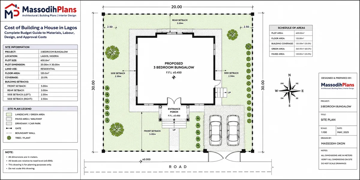
This is the “bird’s eye view” of your entire plot. It shows your land boundaries, the position of the building on the plot, the setbacks (the distance the building must be from the fence), access roads, drainage channels, and sometimes the gatehouse or borehole location.
During my internship, I observed that local planning authorities usually approve this drawing before they consider any other document because it shows how your building relates to neighbouring properties and the government’s approved layout for the area.
In Nigeria, you must obtain this document before you can submit any building plan for approval, whether you apply through LASPPPA in Lagos, the Federal Capital Development Authority (FCDA) in Abuja, the Akwa Ibom State Urban Planning and Development Authority, or your local planning authority.
2. Floor Plan
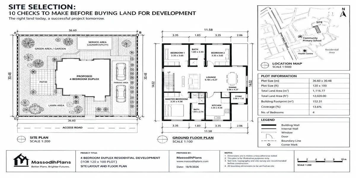
This is the drawing most people are already familiar with, even without knowing the technical name. It is the “top view” of one particular floor of the building showing rooms, walls, doors, windows, and furniture positions. If you have three floors, you will have three separate floor plans: ground floor plan, first floor plan, and so on.
3. Elevations
An elevation shows what the building looks like from outside, from one particular direction front elevation, rear elevation, side elevations. This is the drawing that shows your roof design, window styles, and the overall “face” of the house. Clients usually fall in love with this drawing first because it is the most visually exciting one, but I always tell them: the floor plan is where the real functionality lives.
4. Sections
A section is like slicing the building with a knife and looking inside, vertically. It shows floor-to-floor heights, roof pitch, foundation depth, and how the different levels connect internally especially useful for staircases in a duplex. One challenge I repeatedly encountered during my internship was clients not understanding why staircase headroom matters until I showed them a section drawing and they could finally “see” the problem.
5. Structural Drawings
This shows the “skeleton” of the building columns, beams, foundation type, and reinforcement details. This is not for the untrained eye to interpret casually, but knowing it exists helps you ask your structural engineer the right questions, especially in areas with poor soil or flood-prone locations. This matters a lot in areas with poor soil, like waterlogged parts of Port Harcourt and some low-lying areas in Lagos, where foundation design must respect soil conditions to avoid cracking later.
6. Services/MEP Drawings (Mechanical, Electrical, Plumbing)
This shows where your electrical points, water pipes, and drainage lines run. I have worked with clients who skipped reviewing this drawing entirely, and later regretted it when a sink ended up far from the plumbing line, increasing cost. In Nigeria, this also means planning for generator space, borehole positioning, and inverter/solar setup, since public power supply is not always reliable.
Expert Note: Ask your designer for at least the site plan, floor plan, one elevation, and one section before you commission any building. Anything less means you are building partially blind.
How to Actually Read the Scale (With the Maths)
Almost nobody explains this properly, so let me. A drawing can never be drawn at the real size of the building it has to be shrunk down proportionally, and that proportion is the scale.
If a drawing says 1:100, it means every 1 unit you measure on the paper equals 100 of that same unit in real life. So 1cm on the paper equals 100cm (1 metre) on the actual building. If a wall on the drawing measures 3cm with a ruler, the real wall is 3 metres.
In Nigeria, planning authorities actually fix which scale each drawing type must be submitted at. As a working guide:
- Site plans are typically drawn at 1:100 to 1:200, depending on the size of the plot
- Sections and elevations are typically drawn at 1:50 to 1:100
- Construction details are typically drawn at 1:10 to 1:25
This is exactly why a site plan and a floor plan in the same drawing set can look completely different in “zoom level” they are drawn at different scales on purpose. Always check the scale printed on that specific sheet; don’t assume it matches the last sheet you looked at.
Why Some Lines Are Bold and Others Are Thin
This is a small detail that saves a lot of confusion. Drafters use line weight how thick or thin a line is to tell you what matters most at a glance:
Heavy, bold lines walls, doors, and windows. These are the permanent structure, so your eye should go there first.
Medium lines fixtures like sinks, toilets, and bathtubs, drawn roughly to scale.
Thin or dotted lines furniture, movable items, or things above/below the cut line (like a wardrobe or an overhead cabinet). These are there for reference only; they are not part of what gets built into the structure.
Once you know this, you stop treating every line on a plan as equally important, and you can tell at a glance what’s structural and what’s just suggestion.
The Title Block: The Small Box Everyone Ignores
In most of the world outside the US, dimensions on drawings are given in millimetres (mm) so a wall labelled “150” means 150mm thick, not 150 metres. Always check the drawing’s title block the small information box, usually bottom-right of the sheet. It tells you:
- The project name and client
- The sheet title and sheet number (so you know where this page sits inside the full set)
- The scale used on that specific sheet
- The drafter or architect’s name and registration details
- The revision number and date critical, because a drawing can be revised several times, and building from an outdated revision is a common source of disputes
From what I have seen in practice, ignoring the title block is how people end up assuming a drawing is at the wrong scale, or worse, building from a version that was already replaced.
Beginner Tip: Before asking any question about a drawing, check the title block first. It usually already answers questions about scale, units, and revision number.
Schedules: The Companion Document to the Symbols
Symbols on a floor plan tell you where a door or window is, but not its exact size, material, or how it opens. That’s what schedules are for separate tables usually attached to the drawing set:
Door schedule: lists every door by a tag number, its size, material, and swing direction
Window schedule: lists every window’s size, type, and glazing
Finishes schedule: lists floor, wall, and ceiling finishes room by room
If your designer hands you a drawing set with no schedules, ask for them. Without a schedule, “Door 1” on the plan is just a symbol the schedule is what tells your carpenter exactly what to make.
Common Symbols You Will See On Building Drawings
This is where most people freeze. But once you know these basics, a drawing stops looking like a puzzle and starts looking like a story you can read.
Walls: Shown as thick parallel lines, sometimes shaded or hatched to show material (block work is usually shown differently from concrete).
Doors: A line with a quarter-circle arc showing the swing direction this tells you which way the door opens.
Windows: Shown as a break in the wall line with two or three thin parallel lines across the gap.
North Point: An arrow symbol showing orientation critical in Nigeria’s hot climate for placing windows to catch cross-ventilation and avoid excessive afternoon sun.
Dimension Lines: Lines with arrows and numbers showing exact measurements in millimetres or metres (and sometimes feet, depending on the country’s convention).
Section Cut Line: A bold line with letters (like A-A) on the floor plan, showing exactly where the section drawing has “sliced” through the building.
Electrical Symbols: Small circles for light points, specific icons for switches, sockets, and distribution boards.
Furniture Symbols: Drawn with a lighter line weight than the walls these are for reference, showing how a room is intended to be used, not a fixed instruction.
A Real-Life Example
I once reviewed a plan where a client in Uyo insisted his gatehouse was positioned wrongly on the drawing. When we checked the north point and site plan together, we realised the gatehouse was correctly placed to allow proper vehicle turning radius from the access road he simply hadn’t understood how to read plot orientation on the drawing. This kind of confusion disappears the moment you understand these basics.
Nigerian Submission Requirements You Need to Know
Beyond just reading a drawing, it helps to know what your planning authority actually expects before it will stamp your plan for approval. Requirements vary by state, but as a working example, submissions for planning permission typically require several complete sets of architectural drawings, each signed and sealed by an architect registered to practice in Nigeria not just anyone who can operate AutoCAD. Drawings are usually submitted on a fixed sheet size and bound, and the applicant’s name and property address must be clearly indicated on every panel of the drawing.
This is exactly why I keep telling clients: a beautiful elevation means nothing if the person who drew it isn’t registered, and if the submission doesn’t follow your state’s format, you’ll be sent back to redo it before Development Control even looks at your setbacks.
Reading Dimensions Correctly
In the US, drawings typically use feet and inches instead of millimetres. Whichever convention is used, the units are always stated in the title block, so there’s no need to guess.
Common Mistakes Beginners Make When Reading Drawings
Assuming all drawings use the same scale. A site plan might be at 1:200 while a floor plan is at 1:100 always check the title block on that specific sheet.
Ignoring the north point. This affects how much sun and heat different rooms will get important in tropical climates where ventilation and heat management matter a lot.
Not asking for a section drawing, especially for storey buildings, then being surprised by staircase or ceiling height issues later.
Confusing “as drawn” with “as built.” A drawing shows intent; site conditions (soil, existing structures, drainage) can require adjustments, and a good site supervisor will document these changes.
Ignoring setbacks: many people build right up to the fence, then face demolition threats from planning authorities.
Skipping the schedules and assuming the symbol alone tells the full story of a door or window’s size and material.
Why This Knowledge Protects Your Money
Based on projects I have worked on, clients who understand their drawings even at a basic level ask better questions, catch errors earlier, and have far smoother working relationships with their contractors. This is not about becoming a professional overnight. It is about protecting yourself from silent mistakes that only show up after the concrete has already been poured.
According to the Royal Institute of British Architects, clear and standardised architectural drawing conventions exist specifically so that anyone trained in reading them, regardless of country, interprets the same drawing the same way, which is why these symbols are fairly consistent worldwide.
Frequently Asked Questions
Q: Can I build a house without a proper structural drawing?
This is one of the most common misconceptions I encounter many people assume a floor plan alone is enough. It is not. A structural drawing protects the building’s safety, especially where soil conditions are weak or unpredictable.
Q: What’s the difference between a floor plan and a site plan?
A floor plan shows the inside layout of one level of the building. A site plan shows the entire plot from above, including the building’s position, boundaries, and access.
Q: What does a scale like 1:100 actually mean?
It means 1 unit measured on the drawing equals 100 of that same unit in real life. Measure 5cm on the paper at 1:100 and the real distance is 5 metres.
Q: Do all countries use the same building drawing symbols?
Largely yes, for core elements like walls, doors, and windows, because these conventions were built for universal understanding across the construction industry though local building codes may add specific extra symbols.
Q: Who is allowed to sign a building drawing for approval in Nigeria?
Only an architect registered to practice in Nigeria can sign and seal drawings for submission to a planning authority. A drawing that “looks right” but isn’t signed by a registered professional will not be accepted for approval.
Finally
If there is one thing I would encourage every prospective house owner to do, it is this: never sign off on a project you do not understand. Ask your designer to walk you through the title block, the site plan, the floor plan, at least one elevation, and one section before construction begins. This single habit alone has saved many of my clients from costly regrets.
If you are currently planning your own building and want a properly drafted set of drawings done right from the start, you can explore our full plans library for ready designs, or check our design services if you need something custom-drawn for your exact plot. If you’re new to reading plans altogether, our Plan School section breaks things down even further for beginners. And if this is your first time here, feel free to look around the homepage for more practical guides like this one.
Drop your questions in the comments if any part of your own drawing still confuses you I read every one, and I would genuinely love to help you get it right before you break ground.
Read the following articles to complete the lesson:
- House Plans for Small Plots in Yola: Modern Nigerian Designs Explained
- Architectural Design Principles Every Architect and Homeowner Should Know
- Building Design Guide for Safety, Functional, and Cost-Effective Buildings
- House Interior Design Ideas for Every Room, Style and Budget
- Architectural Drawings Guide: Types, Symbols, Standards, Dimensions and Examples
- Building Drawings Explained: Types, Symbols and Real Construction Examples
- Cost of Building a Modern Bungalow in Calabar (Updated Guide)
- House Plans for Sloping Land in Jos, Plateau State, Nigeria: Smart Nigerian Designs
- Best Roofing Options for Houses in Gusau city of Zamfara State, Nigeria: Prices and Durability
- Master Plan vs Site Plan: Key Differences Every Property Owner Must Know
- Estate Layout Plan Explained for Property Developers and Landowners: Complete Guide
- Cost of Building a 4 Bedroom Duplex in Lagos (Complete Guide)
- Best Roofing Sheets for Nigerian Weather: Complete Guide
- Bungalow vs Duplex: Which is Better to build in Nigeria Today?