Architectural Drawings Guide: Types, Symbols, Standards, Dimensions and Examples
If you have ever opened a full architectural drawing set and felt your head spin too many sheets, too many symbols, too many abbreviations you’ve never seen this guide is for you. In my experience training junior staff and explaining drawings to first-time clients in Uyo and across Akwa Ibom State, the confusion is never really about intelligence. It’s about nobody sitting down to explain the system properly, once, from the beginning. That’s what this guide does.
Quick Answer: Architectural drawings are the technical documents architects, engineers, and contractors use to communicate exactly how a building should be designed and constructed. A complete set typically includes site plans, floor plans, reflected ceiling plans, elevations, sections, roof plans, details, and schedules each following standardized symbols, line weights, and dimensioning rules so that any trained professional, anywhere, reads them the same way.
What’s in This Guide
- What architectural drawings actually are, and why they exist
- The full list of drawing types in a professional set
- Standard symbols you’ll find across every drawing type
- Material hatch patterns how sections show what things are made of
- Drawing standards: line weights, dimensioning rules, and general notes
- How scale and dimensions actually work, with worked examples
- A real-life example from site
- Nigerian standards you need to know
- Common mistakes
- FAQs
What Architectural Drawings Actually Are
An architectural drawing is not decoration it is an instruction document. Every line, hatch, and note on it exists to remove ambiguity between the person who designed the building and the person who is going to physically build it. In my years supervising sites, I have seen how a single unclear dimension line can cause a mason to build a wall 200mm off, which then causes a domino effect on every room after it. A good drawing set removes that guessing entirely.
Architectural drawings are usually produced digitally now, either as flat 2D CAD drawings or as outputs from a 3D Building Information Model (BIM). The difference matters: in a BIM-based set, a door symbol isn’t just a picture it carries data about its size, material, and fire rating behind it. Most practices in Nigeria still work primarily in 2D CAD, but BIM adoption is growing, especially on larger commercial projects.
The Full List of Drawing Types in a Professional Set
Most beginner guides stop at four or five types. A real, professionally issued drawing set usually includes far more:
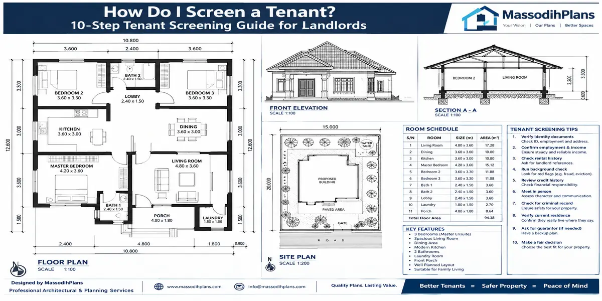
Site plan: the plot from above: boundaries, setbacks, access, drainage, orientation.
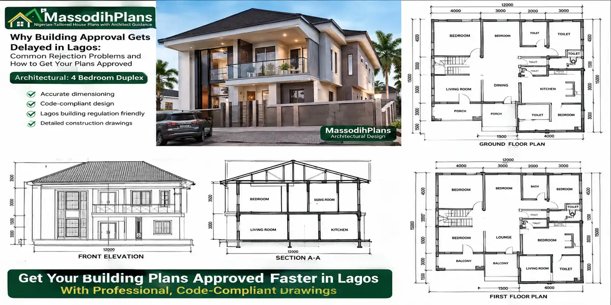
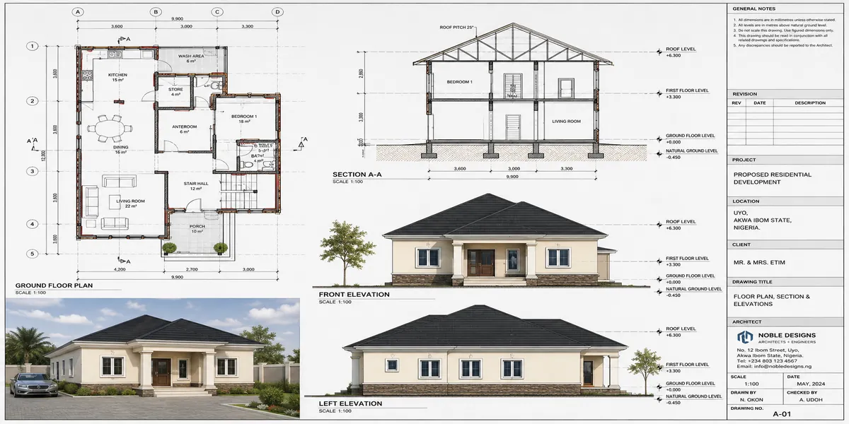
Floor plans: one per level, showing rooms, walls, doors, and windows.
Reflected ceiling plan (RCP): this one surprises most clients. It shows the ceiling as if you flipped the floor plan upward like a mirror, so you can see light fittings, ceiling fans, AC vents, and ceiling levels or drops.
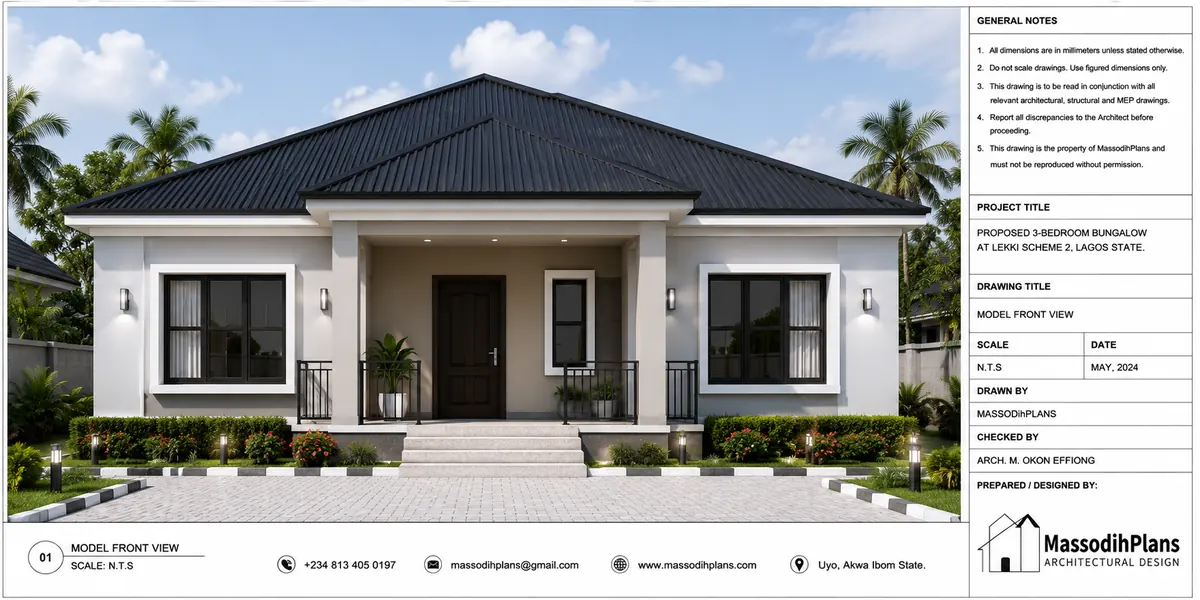
Elevations: front, rear, and side exterior views.
Sections: vertical slices through the building showing heights and internal assembly.
Roof plan: a top-down view of the roof showing slope direction, drainage, and material layout, usually separate from the floor plan.
Details: zoomed-in drawings of tricky junctions: a window head, a staircase nosing, a foundation edge.
Schedules: tables listing every door, window, and finish by tag number, size, and material.
Structural drawings: columns, beams, foundations, and reinforcement, prepared by the structural engineer.
MEP drawings: mechanical, electrical, and plumbing layouts.
Demolition plan: used on renovation projects, showing exactly what’s being removed before new work begins.
Phasing plan: shows how and when different parts of a project will be built, common on larger multi-stage developments.
As-built drawings: produced after construction, recording what was actually built, which sometimes differs from the original design due to site conditions.
Not every small residential project needs all thirteen. A modest bungalow might only need the first eight. But knowing this full list means you’ll never be confused when a bigger commercial drawing set lands in your hands.
Expert Note: If your designer only ever hands you a floor plan and an elevation, ask for the section and the schedules too. Those two documents catch the most expensive mistakes before they happen.
Standard Symbols You’ll Find Across Every Drawing Type
Walls: Thick parallel lines, often hatched to show whether it’s block, concrete, or a partition wall.
Doors: A line with a quarter-circle swing arc showing which way it opens and which side the hinge sits on.
Windows: A break in the wall line with parallel lines across the gap; wider or narrower depending on the window type.
Stairs: Drawn as a series of parallel lines representing each step, with an arrow and the label “UP” or “DN” showing direction of travel this single arrow tells you immediately which floor you’re looking at relative to the stair run.
North point: An arrow, usually placed in the same corner of every floor plan sheet, showing true orientation.
Electrical symbols: Circles for light points, specific icons for single and double switches, sockets, and the distribution board.
Plumbing symbols: Simplified outlines for the WC, sink, shower tray, and bathtub, plus separate line types for water supply versus waste/drainage pipework.
Section cut line: A bold line with letters (A-A, B-B) on a plan, marking exactly where a section drawing has “sliced” through the building.
Material Hatch Patterns: How Sections Show What Things Are Made Of
This is a layer most beginner guides skip entirely, but it’s essential once you’re reading a section or a wall detail. Hatching is a repeating pattern drawn inside a shape to tell you what material that shape represents, without writing it out in words every time:
Concrete: usually shown with small dots or a triangular aggregate pattern
Blockwork/brick: diagonal or brick-coursing hatch lines
Timber (cut): diagonal parallel lines
Insulation: a wavy or zigzag pattern
Earth/ground: hatching combined with a rough, irregular line at ground level
Every legend confirms exactly which pattern the drafter used on that particular set, since firms do vary slightly but once you know the general logic, you can usually guess correctly even without checking.
Drawing Standards: Line Weights, Dimensioning Rules, and General Notes
Line weight hierarchy. Professional drawings use four rough tiers of line thickness, and each tier tells you how important that line is:
Narrow lines: dimension lines and hidden or background details
Standard lines: visible outlines of secondary elements
Wide lines: cut sections and prominent structural elements
Extra-wide lines: emphasis, primary cut lines, and anything the drafter wants your eye to hit first
Dimensioning rules. A few conventions repeat across almost every professional office:
- Dimension text is placed above the dimension line, not floating separately
- Tick marks or small arrowheads mark each end of a dimension line
- Exterior wall dimensions are usually measured from the outer face of the structure to the centre of window and door openings
- Slopes (like a roof pitch or a ramp) are written as a ratio for example, a slope written as 1:10 shows a rise of one unit for every ten units of horizontal run
One rule above all others
Never measure a printed drawing with a ruler to get a “real” dimension if a written dimension already exists on the sheet. Printed sheets shrink or stretch slightly depending on the printer and paper size, so the written number is always the only one you should trust. If a dimension is genuinely missing, that’s a query for the architect not something to estimate off the page.
General notes. Every professional set carries a small block of standard notes, usually near the title block or on the cover sheet. Common ones include:
- All work to conform to applicable building codes and any standards referenced on the sheet
- Contractor to verify existing site conditions and report discrepancies to the architect before proceeding
- Do not scale drawings for dimensions use written dimensions only
- All materials and finishes to be installed per manufacturer’s recommendations unless otherwise noted
These notes exist because no drawing can cover every possible site condition, so they place responsibility on the builder to flag anything that doesn’t match what’s drawn, rather than guessing and continuing.
How Scale and Dimensions Actually Work
A drawing is always a shrunk-down, proportional version of the real building never the real size. If a drawing is at 1:100, every 1 unit measured on the paper equals 100 of that same unit in real life. Measure 3cm on the sheet and the real distance is 3 metres.
Most professional sheets include both a written scale (such as “1:100”) and a small graphic scale bara short ruler-like line printed directly on the drawing. The graphic bar solves a common problem. People often resize drawings during printing, scanning, or PDF sharing, and those changes quietly make the written scale inaccurate. Because the graphic bar forms part of the drawing itself, it resizes with the drawing and remains accurate regardless of the print size. If you ever have to choose, trust the graphic scale bar instead of the written number.
Architects usually draw a typical floor plan as a horizontal cut about 1.2 metres above the finished floor level. This cut explains why doors and windows appear the way they do on a plan. If a plan uses an unusual cut height for example, to reveal a mezzanine it should always carry a clear label that identifies the difference.
A Real-Life Example
On a duplex project in Uyo, the contractor once questioned why the roof plan directed drainage toward the rear of the building when the client expected it to flow toward the front. We reviewed the roof plan and the section together and quickly confirmed the reason. The design intentionally directed water away from the entrance walkway and toward a soak-away at the rear boundary. Without a separate roof plan, no one would have noticed that critical design decision until rainfall exposed the problem.
Nigerian Standards You Need to Know
Requirements vary by state, but this example reflects common planning authority expectations. Most authorities require applicants to submit multiple complete sets of architectural drawings. A registered architect licensed to practise in Nigeria must sign and seal every set. Applicants must also use the required sheet size and bind the documents properly. Authorities commonly specify drawing scales as well. Site plans usually use scales between 1:100 and 1:200, sections and elevations between 1:50 and 1:100, and construction details between 1:10 and 1:25. Development Control usually returns any drawing set that falls outside these scale ranges or lacks the signature and seal of a registered architect before reviewing setbacks, regardless of the quality of the design.
Common Mistakes
Assuming one drawing type tells you everything a floor plan alone hides ceiling information, roof drainage, and structural sizing.
Measuring a printed sheet with a ruler instead of trusting the written dimension or the graphic scale bar.
Ignoring the reflected ceiling plan, then being surprised by light or AC positions that don’t match furniture layout.
Skipping the general notes block and missing an instruction that directly affects site work.
Assuming symbols are identical across every firm’s drawings always check that specific set’s legend first.
Why This Knowledge Protects Your Money
Clients and contractors who understand the full drawing set not just the floor plan catch conflicts before they become expensive change orders. A ceiling light clashing with a beam, a roof fall going the wrong way, a missing dimension that gets guessed on site all of these are cheap to fix on paper and expensive to fix in concrete.
Frequently Asked Questions
Q: What’s the difference between a floor plan and a reflected ceiling plan?
A floor plan shows what’s happening at roughly waist height looking down. A reflected ceiling plan shows the ceiling above, as if it were mirrored downward onto the same sheet lighting, fans, AC vents, and ceiling drops.
Q: Why do drawings have both a written scale and a graphic scale bar?
Because printed or scanned drawings can shrink or stretch slightly. The graphic bar resizes with the image itself, so it stays accurate even when the written scale no longer matches the printed size.
Q: What does a slope written as 1:10 mean?
It means a rise of one unit for every ten units of horizontal distance the same ratio logic used for drawing scale, just applied to a slope instead of a plan.
Q: Do I need all 13 drawing types for a small house?
No. A modest residential project typically needs the site plan, floor plans, elevations, sections, structural drawings, and schedules. Reflected ceiling plans, phasing plans, and demolition plans usually only appear on larger or more complex projects.
Q: Who can sign architectural drawings for approval in Nigeria?
Only an architect registered to practice in Nigeria can sign and seal a drawing set for submission to a planning authority.
Finally
A drawing set is a conversation, not a single document. The floor plan tells you the layout, the section tells you the heights, the ceiling plan tells you what’s overhead, and the schedules tell you the exact specification of every door and window. Read them together, in the right order, and very little on site will ever surprise you.
If you are currently planning your own building and want a properly drafted, complete drawing set done right from the start, you can explore our full plans library for ready designs, or check our design services if you need something custom-drawn for your exact plot. If you’re new to reading drawings altogether, our Plan School section breaks things down even further for beginners. And if this is your first time here, feel free to look around the homepage for more practical guides like this one.
Drop your questions in the comments if any part of a drawing set still confuses you I read every one, and I would genuinely love to help you get it right before you break ground.
Read the following part of this lesson below:
- Best Roofing Options for Houses in Gusau city of Zamfara State, Nigeria: Prices and Durability
- Building Drawings Explained: Types, Symbols and Real Construction Examples
- Cost of Building a Modern Bungalow in Calabar (Updated Guide)
- House Plans for Sloping Land in Jos, Plateau State, Nigeria: Smart Nigerian Designs
- House Plans for Small Plots in Yola: Modern Nigerian Designs Explained
- Architectural Design Principles Every Architect and Homeowner Should Know
- Building Design Guide for Safety, Functional, and Cost-Effective Buildings
- House Interior Design Ideas for Every Room, Style and Budget
- Building Drawings Explained: Types, Symbols and Real Construction Examples
- Cost of Building a Modern Bungalow in Calabar (Updated Guide)
- House Plans for Sloping Land in Jos, Plateau State, Nigeria: Smart Nigerian Designs
- Bungalow vs Duplex: Which is Better to build in Nigeria Today?
- Cost of Building a 4 Bedroom Duplex in Lagos (Complete Guide)
- Best Roofing Sheets for Nigerian Weather: Complete Guide
- How to Practically Draw and Design a Duplex for Small Plots