The Building Drawing Most Beginners Skip and Why It Could Save Your Project
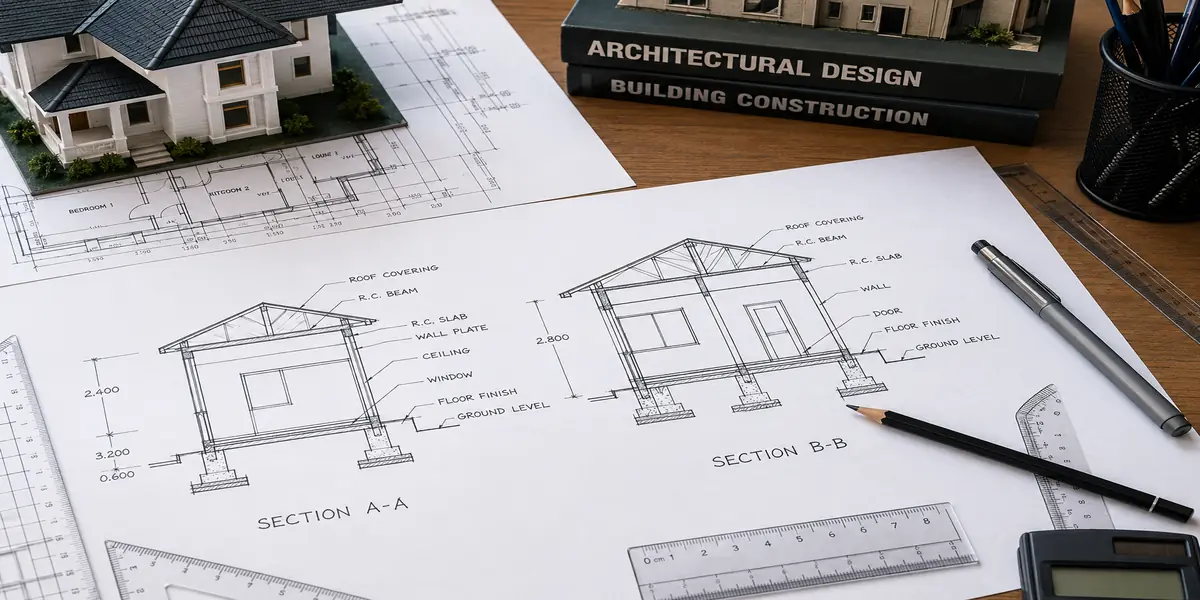
How to Draw a Building Plan Section A-A, B-B
You want to know how to draw a building plan section A-A, B-B, here is the short answer first: a section is a vertical “cut” through your building plan, drawn to reveal what’s happening from the foundation up to the roof along a specific line you mark on your floor plan (that’s your A-A or B-B cut line). You draw it by projecting heights directly from your floor plan and elevation, showing floor levels, ceiling heights, roof pitch, and internal details like staircases, exactly where that cut line passes through. Now let’s go slowly through it, step by step, the way I would explain it to someone learning this for the first time.
I know why you are here. A lot of people can draw a floor plan and even manage an elevation, but the moment “Section A-A” comes up, confusion enters. And I understand why a section is the one drawing that forces you to think in three dimensions, not just flat on paper. This is not a small matter, because I have seen it happen: a building without a properly thought-through section ends up with wrong ceiling heights, staircases that don’t fit, or floor levels that don’t match on site. Especially now that plots are shrinking in our cities and every centimeter of height and space matters, understanding sections properly is not optional again it is one of the most important skills in this profession.
What Exactly Is a Building Section, and Why Does It Matter So Much?
In my experience, many beginners think of a section as just “another drawing” to complete a set. That thinking is what causes problems later. A section is actually where your floor plan and your elevation are forced to agree with each other it shows you, and shows the builder, exactly how tall each floor is, where the roof sits, how the staircase rises, and how everything lines up vertically. Based on projects I have worked on, most on-site height and level mistakes happen because nobody drew (or properly read) a clear section before construction started.
Understanding the A-A, B-B Naming System
Before we draw anything, let’s clear up the confusion around the naming.
On your floor plan, you draw a straight line through the part of the building you want to “cut” and see inside.
Each end of that line gets a letter, and the same letter is repeated at both ends (A on one end, A on the other), which is why we call it “Section A-A.”
If you need a second cut through a different part of the building maybe through the staircase this time you use the next letter, “B-B,” and so on.
The direction of the small arrows at each end of the line tells you which way you are “looking” when you view that section.
One lesson I learned early is that these letters are not decorative they are instructions. Anyone reading your drawing set should be able to look at “Section A-A” and immediately locate that exact cut line back on the floor plan.
Step 1: Choose Your Section Cut Lines Wisely
This is the step most beginners rush, and it’s where a good section starts.
Choose a cut line that passes through the most information-rich parts of the building typically through the staircase, a bathroom, and a main living space if possible, all in one line.
If one cut line can’t capture everything important, that’s exactly why you’re allowed a second one (B-B) through another critical area.
Mark your section line directly on the floor plan, with the arrows showing viewing direction, before you attempt to draw the actual section.
Common Beginner Mistake: Choosing a section line that passes through a boring, empty part of the building instead of through the staircase or a room with a changing ceiling height. A section is only useful if it cuts through something worth showing.
Step 2: Drawing a Building Section Manually — Step by Step
For beginners who want to understand the logic before jumping into software, here is the manual approach.
Set up your baseline first this represents your finished floor level, drawn as a straight horizontal line at the bottom of your sheet.
Project your floor-to-ceiling height upward from the baseline, typically 3.0m for a standard living space, though this can vary based on your design.
Draw your floor slab thickness between levels if it’s a multi-story building, typically around 150mm to 225mm depending on your structural design.
Project the staircase if your cut line passes through it mark each step’s rise and going, projecting the step positions upward and across in sequence, matching exactly what you drew on your floor plan.
Draw your roof structure at the top, showing the roof pitch angle and how it sits above the top ceiling level, including any ceiling void or roof space.
Add ground-level details below the baseline, such as foundation depth and damp-proof course, if your project requires showing substructure information.
Step 3: Drawing a Building Section in AutoCAD — Step by Step
Once you understand the manual logic, AutoCAD lets you execute the same thing with more accuracy and speed.
Reference your floor plan and elevation as base layers, and create a dedicated new layer for your section drawing, so it stays clean and separate.
Draw your section cut line directly on the floor plan using PLINE, and label both ends with matching letters (A and A, or B and B) using MTEXT.
Set up your baseline in the section drawing using LINE, representing finished floor level, aligned to the same horizontal reference across your whole drawing set.
Use OFFSET to project floor-to-ceiling heights, slab thicknesses, and roof levels upward, keeping every measurement consistent with your elevation drawing.
Draw the staircase in section using LINE and OFFSET to represent each step’s rise and going accurately, cross-checking against your floor plan staircase dimensions.
Use DIMLINEAR to dimension all vertical heights floor-to-ceiling, slab thickness, parapet or roof height — so a builder can read exact figures directly off the drawing.
Hatch solid elements (walls, slabs, foundation) using the HATCH command, so cut surfaces are visually distinct from open space in the section.
Add a title block label (“Section A-A”) beneath the drawing, consistent with your other sheets, and confirm it matches the cut line marked on your floor plan.
Common Beginner Mistake: Drawing the section heights from imagination instead of projecting them directly from the elevation and floor plan. If your section doesn’t align exactly with your other drawings, a builder will find the contradiction on site, usually at the worst possible time.
Nigerian Reality Layer: What You Must Consider Beyond the Drawing
This is the part most tutorials skip, and it’s exactly where real projects succeed or fail on site.
Unstable material prices: Floor slab and staircase construction involve significant concrete and reinforcement work. From what I have seen in practice, finalizing your section early lets you get accurate quantities for early material sourcing before prices shift again.
Power supply realities: If your section shows details requiring site fabrication (like steel staircase elements), plan around your available power supply for that stage of work.
Flooding and drainage: Your section should clearly show finished floor level relative to the surrounding ground level I have encountered this situation multiple times where a building was set too low relative to the compound, and flooding became a permanent headache that a properly drawn section would have caught early.
Ventilation needs and heat management: Your section is where you can properly show ceiling height and roof void space, both of which significantly affect indoor heat taller ceilings and ventilated roof spaces keep interiors noticeably cooler.
Compound security and gatehouse positioning: If your gatehouse has a different floor level or roof height from the main building, a separate section through it avoids confusion during construction.
Generator space and borehole planning: If these are housed in a structure with its own roof or floor level, make sure their section details are drawn separately rather than assumed to match the main building.
Small Plot Optimization: Sections on Tight Plots
On a small or narrow plot, sections carry extra weight:
Vertical space maximization: Where land is limited, some designs go upward instead of outward. A well-drawn section is what proves whether your proposed additional floor is actually comfortable to live in, not just theoretically possible.
Staircase efficiency: On small plots with tight internal circulation, the section is where you confirm your staircase doesn’t consume more space than necessary while still meeting comfortable rise-and-going standards.
Compact luxury concepts: A section showing generous ceiling height in key rooms, even on a modest footprint, is often what makes a small home feel premium rather than cramped.
Human Lifestyle Layer: How Sections Affect Daily Living
Family lifestyle suitability: Ceiling heights and floor level changes shown in section directly affect how comfortable a home feels day to day, especially in warmer climates.
Children’s movement: If your section reveals a steep or oddly proportioned staircase, that’s a safety concern worth catching on paper, not after the stairs are cast in concrete.
Guest privacy: Where a section shows a split-level design separating guest and family areas, confirm the level changes don’t create awkward, unintended sightlines between spaces.
Elderly accessibility: A section is exactly where you catch whether ground floor rooms intended for elderly family members have manageable level changes, or whether steps have crept in where a flat transition was intended.
Work-from-home considerations: If a section shows a mezzanine or loft space intended as a home office, confirm the headroom is genuinely usable and not just visually present in the drawing.
Future family growth: If you’re planning to add a floor later, your section should show the current roof and floor structure in a way a structural engineer confirms can support that future addition.
Construction Experience Layer: What Builders Usually Get Wrong
While assisting with development control activities, I witnessed firsthand how often site work drifts from the drawn section without anyone noticing until much later.
Contractor mistakes: Building floor-to-ceiling heights “by feel” instead of checking the section drawing at each level, leading to inconsistent heights between floors.
Material waste prevention: A clearly dimensioned section helps contractors order the correct quantity of blocks, concrete, and reinforcement for each level, reducing wasteful over-ordering or costly shortages.
Supervision tips: Always confirm actual site levels against the section drawing at every floor slab stage, not just at the final finish I have seen buildings where an error at an early floor level only became obvious much later, when it was far more expensive to correct.
Structural planning awareness: A section shows architectural intent floor levels, ceiling heights, roof form. It does not replace structural drawings, and reinforcement or slab design should always be confirmed separately by a structural engineer.
Cost Estimate Considerations
Your section decisions influence cost more than most beginners realize:
Number of floors and floor-to-floor height: Every additional 100mm of ceiling height across an entire floor area adds to wall and material cost, so height decisions in your section should be intentional, not arbitrary.
Staircase design complexity: A straight staircase shown in section is generally more economical to construct than a complex winding or split-level staircase.
Roof void and structure: How your section handles the roof void affects both material use and long-term heat performance, which ties back into cost through comfort and possible future cooling expenses.
Experience has taught me that clients who confirm their section early, with all levels properly checked against the floor plan and elevation, avoid the costly on-site corrections that come from discovering a height problem mid-construction.
Investment Layer: Why Your Section Affects Long-Term Value
Resale potential: Comfortable, well-proportioned ceiling heights (clearly shown and achieved through a good section) significantly affect how a building feels and is valued by future buyers.
Rental profitability: Section-driven decisions like ventilation and heat management directly affect tenant comfort, which in turn affects how easily and consistently a property can be rented out.
Estate suitability: If your project sits within an estate with height or roofline guidelines, your section is the drawing that proves compliance before construction begins.
Long-term practicality: A section that properly accounts for drainage, floor levels, and ventilation protects the building from costly recurring problems for decades.
Common Mistakes to Avoid When Drawing a Building Section
Choosing a cut line through an unimportant part of the building instead of the staircase or key spaces
Drawing section heights from memory instead of projecting them from the floor plan and elevation
Forgetting to dimension floor-to-ceiling heights and slab thicknesses clearly
Ignoring finished floor level relative to surrounding ground level
Treating the section as decorative rather than as a coordination tool between floor plan, elevation, and structural drawing
Skipping a second section (B-B) when one cut line genuinely cannot show everything important
Frequently Asked Questions
What is the difference between Section A-A and Section B-B?
They are simply two different cut lines through different parts of the same building, each labeled with its own matching letter pair so the drawings can be clearly referenced back to the floor plan.
Can I draw a building section without AutoCAD?
Yes. The manual method covered above teaches the same core logic baseline, projected heights, staircase, roof which you can execute by hand before or instead of using software.
Does a section replace a structural drawing?
No. A section shows architectural intent heights, levels, and form. Structural design, reinforcement, and load calculations must be confirmed separately by a structural engineer.
Why does my section not match my elevation?
This usually means heights were estimated instead of properly projected from one drawing to the other. Always draw your section by projecting directly from your floor plan and elevation, not from memory.
How many sections does a typical building need?
It depends on complexity, but most residential projects need at least one section through the staircase, with additional sections added wherever the building has important level changes or features not visible in the first cut.
Final Thoughts
I did not learn this from a textbook alone both classroom learning and years of field observation support everything covered in this article. A building section is not just another drawing to complete your set; it is the drawing that forces your floor plan, elevation, and construction reality to agree with each other before a single block is laid. Take your time choosing your cut lines, project your heights properly, and don’t treat this drawing as optional on many projects, it is the one drawing that catches a costly mistake before it becomes permanent.
If you want to see these principles applied to real, ready-made designs, browse our plans library for layouts across different plot sizes, or explore our plan school section for more step-by-step lessons like this one. If you’re working on your own project and want expert support getting your sections right, our design services are there to help directly. And if this is your first time here, start from our homepage (massodihplans.com) to see everything we offer.
- Architectural Engineering and Architectural Design Courses for House Building Plans
- Cost of Blocks, Cement, Iron Rod and Roofing Sheets in Uyo: Real Prices From the Field Now
- Cost of Roofing a 4 Bedroom Duplex in Abakaliki (Complete Guide)
- Nigerian Building Approval Checklist for Overseas Property Owners
- How Is a Modern Court Building Designed for Safety and Efficiency? (Complete Guide)
- How to Draw Building Elevations Step by Step (Manually and in AutoCAD): Complete Guide for Beginners
- How Do You Design a Functional Mosque Building Plan Step by Step?