How to Draw a Fence Layout Plan Correctly
How to Draw a Fence Layout Plan Correctly: Boundary, Wall Offset, Pillar Spacing and Gates (With a Worked Plot Example)
To draw a fence layout plan correctly, start from your surveyed plot boundary and never from your house. Draw it to a fixed scale (1:100 suits most residential plots). Pull the wall centreline inside the boundary by half the footing width plus a small clearance. Space the pillars in equal bays no longer than your engineer allows. Draw every gate with its clear opening and its swing arc. Then dimension everything, number the beacons, and add a scale bar, north arrow and notes. A plan built this way lets a bricklayer set out the fence without guessing, and it keeps every block of the wall on your own land.
Here is the number that changed how I draw fences. On a standard 15 m x 30 m plot, a 225 mm block fence with a proper footing quietly eats about 42 m² of your land. That is more than three parking spaces. Draw the fence carelessly and you lose even more, or you push the footing across the boundary and hand your neighbour a free wall.
I have watched fences go up with no drawing at all, only a mason saying “we go follow the line.” Sometimes that works. When it fails, it fails at the worst moment, after the pillars are cast and the money is spent. By the end of this post you will have a drawing method, the formulas behind it, a fully worked 15 m x 30 m example, a quantity take-off you can read straight off your plan, and the one drawing mistake that is almost impossible to fix once concrete has set. I will name that mistake plainly when we get to it.
Since this site exists to help people get the best from small plots, I will keep one question in front of us the whole way: how do you draw a fence that protects your land without swallowing it?
The Eight-Step Version (Pin This Before We Go Deeper)
- Collect your survey plan, beacon numbers, approval conditions and the structural details of the wall.
- Pick a scale and sheet size so the smallest thing you need to show is still readable.
- Draw the plot boundary exactly as the survey gives it, and check it closes.
- Draw the wall centreline inside the boundary using the offset formula.
- Divide each run into equal bays and mark the pillars.
- Draw gates with their opening width and swing or slide space.
- Add levels, drainage openings, corner clearances and neighbour conditions.
- Dimension, label, add a legend, and run the final checks.
Now let us take them one at a time, starting with a question that trips up a lot of people.
What Is a Fence Layout Plan, and How Is It Different From a Site Plan?
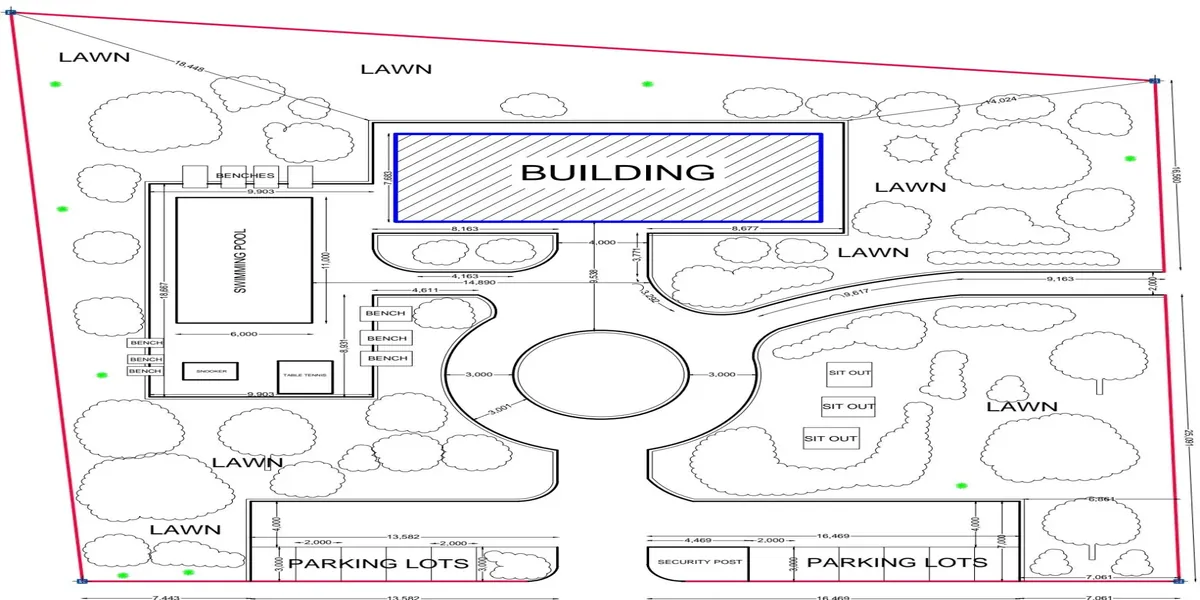
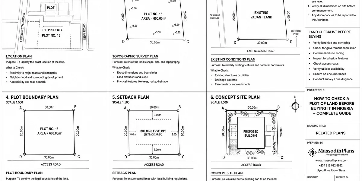
A fence layout plan is a top-down drawing that shows where the boundary wall or fence sits on your plot, where its pillars fall, where the gates are, and how long each run is. People confuse it with three other drawings, so here is the difference:
| Drawing | Made by | What it shows | Can a builder set out a fence from it? |
|---|---|---|---|
| Survey plan | Registered surveyor | Legal boundary, beacon positions, bearings, distances, area | No. It shows the land, not the fence |
| Site plan | Architect or planner | House position, setbacks, access, plot features | Not precisely. It rarely shows pillars or gate details |
| Fence layout plan | Designer, draughtsman or you | Wall line, pillars, bays, gates, offsets, dimensions | Yes, if drawn correctly |
| Fence elevation and section | Designer | Height, footing depth, pillar size, wall build-up | Needed alongside the layout |
The layout plan is the one that answers “where exactly do I dig?” Much of what ranks online for this topic is written for American backyards, where the job is to sketch a rough perimeter for a quote. That is fine for a wooden fence. It is not enough for a sandcrete block wall with a reinforced footing, because the wall has a thickness and a foundation, and both have to fit inside your boundary. That detail is the heart of this guide, and it matters in every country.
What to Put on Your Table Before You Draw a Single Line
Good drawings are mostly good preparation. Gather these first:
- Survey plan with beacon numbers, bearings, distances and the stated area. If you do not have one, do not draw a fence yet. Call a registered surveyor.
- Approved building plan or site plan, so the fence agrees with the house, setbacks and access shown there.
- Wall specification from your engineer or builder: block size, wall height, footing width, pillar size.
- Gate decision: swing or sliding, single or double, and the clear opening you need.
- Neighbour situation: existing walls, shared walls, anything leaning on or near your line.
- Ground levels: even a rough idea of where the plot rises and falls, and where water goes when it rains.
- Utility lines crossing the plot, such as water pipes and cables. Wherever you live, locate them before you dig.
Those preparation steps match how fencing professionals describe the job elsewhere. Fence layout includes establishing control points and computing post spacing from the total run length and the chosen bay size. We will do exactly that, with numbers, a little further down. fencefast
Fence lines follow the property boundary, never the edges of the building. If your drawing starts with the house and the fence is sketched around it afterwards, you are building on a guess. Always start from the survey.
Choosing Your Scale and Sheet Size
Now that your documents are ready, decide how big the drawing will be on paper. The formula is simple:
Drawing length (mm) = Real length (mm) ÷ Scale denominator
For our 30 m plot:
| Scale | 30 m draws as | 15 m draws as | Smallest sheet that fits | A 450 mm pillar shows as |
|---|---|---|---|---|
| 1:200 | 150 mm | 75 mm | A4 | 2.3 mm (too small) |
| 1:100 | 300 mm | 150 mm | A3 | 4.5 mm (good) |
| 1:50 | 600 mm | 300 mm | A1 | 9 mm (very clear) |
Choose the scale from the smallest object you must show, not from the sheet you happen to have. A pillar below about 3 mm on paper turns into a dot. For most residential plots, 1:100 on A3 is the sweet spot. Always draw a scale bar as well. When someone photocopies or resizes your drawing, the “1:100” note becomes a lie, but a bar printed on the sheet shrinks with the drawing and stays true.
Step 1: Draw the Plot Boundary Exactly as the Survey Gives It
Everything else hangs on this line, so take your time here.
For a rectangular plot, draw the two sides and the two ends at the surveyed lengths. Then check squareness with the diagonals. For a 15 m x 30 m plot:
Diagonal = √(15² + 30²) = √(225 + 900) = √1125 = 33.54 m
Both diagonals must equal 33.54 m. If your drawing or your ground measurement gives two different diagonals, the shape is a parallelogram, not a rectangle, and something is wrong.
For an irregular plot, use the coordinates or bearings and distances from the survey, and check your drawn shape against the stated area with the shoelace formula:
Area = ½ × |Σ (xᵢ × yᵢ₊₁ − xᵢ₊₁ × yᵢ)|
Test it on our rectangle with corners (0,0), (15,0), (15,30), (0,30):
- 0×0 − 15×0 = 0
- 15×30 − 15×0 = 450
- 15×30 − 0×30 = 450
- 0×0 − 0×30 = 0
- Sum = 900, so area = ½ × 900 = 450 m² ✓
If your drawn polygon gives an area different from the survey’s stated area, find the error before going further. For a closed shape with n sides, the interior angles must also add up to (n − 2) × 180°. A four-sided plot gives 360°.
Mark each beacon with its survey number (B1, B2, and so on) and draw it as a small filled circle. If a beacon has gone missing on the ground, do not guess its position. Ask the surveyor to re-establish it first.
Step 2: Decide Where the Wall Sits (The Offset Most People Skip)
This is the step the earlier teaser was about.
A wall is not a line. It has thickness, and it stands on a footing that is wider than the wall. If you draw the wall line on the boundary line, the footing lands partly on your neighbour’s plot. That is the mistake I said was nearly impossible to fix. You cannot undo a cast footing quietly. You break it out or you argue about it.
The fix is the offset formula. Let:
- F = footing width
- c = clearance from the boundary (I use 25 to 50 mm)
- t = finished wall thickness (block plus plaster)
Wall centreline offset from boundary: d = F ÷ 2 + c
Inner face offset from boundary: D = d + t ÷ 2
Worked example. A 225 mm block wall plastered both sides gives t = 0.25 m. Suppose your engineer specifies a 600 mm wide footing, and you keep 50 mm clearance.
- d = 0.600 ÷ 2 + 0.050 = 0.350 m
- D = 0.350 + 0.125 = 0.475 m
Draw the wall centreline 350 mm inside the boundary, all the way round.
Remember that the footing width comes from your structural engineer, not from this article. I am using 600 mm as an example. Use the number on your engineer’s detail.
The “Fence Tax” on a Small Plot
Now for the number from the introduction. The usable ground inside the wall is:
Net area = (W − 2D) × (L − 2D)
For our 15 m x 30 m plot with D = 0.475 m:
Net area = (15 − 0.95) × (30 − 0.95) = 14.05 × 29.05 = 408.15 m²
Land lost to the fence = 450 − 408.15 = 41.85 m², which is 9.3% of the plot.
Here is how the choice of wall changes it:
| Wall option | Footing F | Wall t | D | Net area inside | Land lost |
|---|---|---|---|---|---|
| 225 mm block, plastered | 600 mm | 0.25 m | 0.475 m | 408.15 m² | 41.85 m² |
| 150 mm block, plastered | 450 mm | 0.175 m | 0.363 m | 417.90 m² | 32.10 m² |
I am not telling you to thin your wall. A perimeter wall must be strong enough for its height and for security, and your engineer decides that. I am showing you what every centimetre costs, because on a 450 m² plot you are buying land at a price per square metre and then feeding part of it to a wall. If you are weighing a smaller footprint house against a thinner fence, put these numbers beside your house plan before deciding.
The pillars stick further into the plot than the wall does. A 450 mm pillar on a 250 mm wall projects about 100 mm on each face. Draw pillars at their true size, because a gate or a parked car can clip a pillar you forgot to show.
Step 3: Place the Pillars and Divide Each Run Into Equal Bays
Next we divide the wall into bays. The goal is equal spacing with no awkward short panel at a corner.
Number of bays: n = ⌈L ÷ s_max⌉ (round up)
Actual spacing: s = L ÷ n
Here L is the length of the run (centreline to centreline) and s_max is the maximum bay your engineer allows. On site, 2.5 to 3.0 m is common for a 225 mm wall of ordinary height. Treat that as a starting point, and let your engineer confirm it for your height and soil.
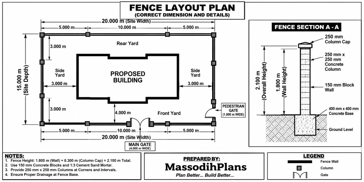
Our centreline rectangle is (15 − 0.70) by (30 − 0.70) = 14.30 m by 29.30 m. Perimeter = 2 × (14.30 + 29.30) = 87.20 m.
The gate. Say we place a 3.6 m clear double gate in the front wall with 450 mm gate pillars. The pillar centres sit 3.6 + 0.45 = 4.05 m apart. If the gate is central, each front half-run is (14.30 − 4.05) ÷ 2 = 5.125 m.
Using s_max = 3.0 m:
| Run | Length L | Bays n = ⌈L ÷ 3.0⌉ | Spacing s = L ÷ n |
|---|---|---|---|
| Front, each side of gate | 5.125 m | 2 | 2.56 m |
| Each side wall | 29.30 m | 10 | 2.93 m |
| Rear wall | 14.30 m | 5 | 2.86 m |
Total bays = 2 + 2 + 10 + 10 + 5 = 29.
Pillar count has a simple self-check. Because the gate gap breaks the loop into an open chain, pillars = bays + 1 = 30. Count them on your drawing independently (4 corners, 2 gate pillars, 2 front intermediates, 18 on the sides, 4 on the rear = 30 ✓). If your count and the formula disagree, your drawing has an error.
Wall line length = 87.20 − 4.05 = 83.15 m. Keep that figure, because we will use it shortly.
Step 4: Draw the Gates So They Actually Work
A gate drawn as a gap in the wall is where plans fail in real life. Show these things:
- Clear opening width, measured between the faces of the gate pillars, not centre to centre
- Swing arcs for swing gates, drawn at the leaf length
- Run-back length for sliding gates, which needs a length of free wall beside the gate
- Pedestrian gate, if separate, with at least 0.9 to 1.0 m clear
For a double swing gate over a 3.6 m opening, each leaf is 3.6 ÷ 2 = 1.8 m, so the arc radius is 1.8 m. The ground each quarter-circle sweeps is π × r² ÷ 4 = 3.1416 × 1.8² ÷ 4 = 2.55 m². Both leaves need about 5.1 m² of clear ground inside the gate. Check that area against your parking bays, your generator house and any planting. In a small plot, the gate arc and the car often want the same square metres, so this check belongs on the drawing.
If a gate swings outward, check that it does not sweep across a footpath or road. Many authorities do not allow that, so draw gates swinging inward unless you have confirmation otherwise. For a sliding gate, the free run-back is roughly the opening plus extra for the gate’s frame and motor. Ask your gate maker for the actual figure before you fix the pillar positions.
A small lifestyle point before moving on. On narrow plots, put the gate off-centre toward the side where your driveway will run. That keeps the other side of the frontage free for a planting strip or a bin store instead of dividing the front yard in the middle.
Step 5: Corners, Slopes and Drainage (Where Real Plots Differ From Textbook Plots)
Everything so far assumed a flat, mid-block plot. Real plots are not so obliging, so here are three situations to draw for.
Corner plots: the visibility triangle. At a road junction, a tall solid wall at the corner blocks a driver’s view of cross traffic. Many authorities require a clipped corner or a lower wall there. If your authority specifies a 3 m x 3 m splay, the cut-off triangle has a hypotenuse of 3√2 = 4.24 m and removes ½ × 3 × 3 = 4.5 m² from the corner. Authorities set their own figures, so confirm yours and draw the splay on the plan.
Sloping plots: stepped panels. Calculate the gradient first:
Gradient (%) = fall ÷ run × 100
Suppose the plot falls 1.2 m across its 30 m length. Gradient = 1.2 ÷ 30 × 100 = 4%. With 2.93 m bays, the fall per bay is 2.93 × 0.04 = 0.117 m. A block course with its joint is about 0.235 m, so stepping the wall down one course every two bays matches the ground almost exactly (2 × 0.117 = 0.234 m). Mark the step positions on the plan and note the level at each pillar.
Drainage. A solid wall across a natural water path becomes a dam. Where water flows through or along the plot, draw drainage openings or weep points at the low ground, and show where the water goes on the outside. The inside of the plot needs somewhere for rain to leave, because a walled compound with no outlet fills like a basin.
Step 6: Dimensions, Symbols and Notes (So Nobody Has to Phone You)
A drawing a builder cannot read gets “interpreted,” and interpretation is how walls end up in the wrong place. Use three dimension strings:
- Overall: full plot length and width.
- Pillar spacing: centre-to-centre of every bay, written once per run if the spacing is equal (“10 bays @ 2.93 m c/c”).
- Offsets: boundary to wall centreline (350 mm in our example), and gate opening widths.
Here is a line convention I use, which you can adapt to your authority’s legend:
| Element | Suggested symbol |
|---|---|
| Plot boundary | Heavy dash-dot line |
| Fence wall (plan) | Thick continuous double line at true wall thickness |
| Pillar | Filled square at true size |
| Beacon | Filled circle with number |
| Gate swing | Thin quarter-circle arc with leaf shown |
| Setback line | Medium dash-dot line, labelled |
| Neighbour’s existing wall | Thin dashed line, labelled “existing” |
| Drainage opening | Small rectangle with arrow showing water direction |
Then add the items people forget: north arrow, scale bar, title block, date, units (state “all dimensions in metres” or “in mm”), and a short notes box (wall height, block size, footing detail reference, “do not scale from this drawing”). Mixing metres and millimetres on one sheet is a classic way to build a wall ten times too long, so pick one unit for the plan and state it.
Step 7: Read Your Quantities Straight Off the Drawing
A correct fence layout plan pays for itself the moment you ask for quotations, because every contractor now prices the same job. From our worked example:
| Item | Quantity | Source on drawing |
|---|---|---|
| Wall line length | 83.15 m | Centreline length |
| Pillars | 30 | Count and bays + 1 check |
| Bays | 29 | Dimension strings |
| Gate | 1 double leaf, 3.6 m clear | Gate note |
| Area lost to fence | 41.85 m² | Offset calculation |
For blockwork, work out blocks per square metre. A 450 x 225 mm block laid with 10 mm joints occupies 0.46 × 0.235 = 0.1081 m² of face, so:
Blocks per m² = 1 ÷ 0.1081 ≈ 9.25
For every 10 m of infill wall that is 2.1 m high: 10 × 2.1 = 21 m², then 21 × 9.25 ≈ 194 blocks, and about 204 with 5% wastage. Subtract the pillars and gate openings from your total wall length before you multiply, or you will over-order. Treat all of this as a planning estimate and let your quantity surveyor or builder confirm it with current prices.
From Paper to Ground: Setting Out Without a Total Station
Your drawing is only useful if the ground matches it. Take the plan to site and follow this order:
- Locate the beacons and string the boundary between them.
- Measure the offset (350 mm in our case) inward from the string to mark the wall centreline.
- Make the corners square using the 3-4-5 rule. A triangle with sides 3, 4 and 5 m contains a right angle, because 3² + 4² = 5². Bigger is better. Use 6-8-10 or 9-12-15 so small taping errors shrink relative to the triangle.
- Check both diagonals of your centreline rectangle. In our example, √(14.30² + 29.30²) = √1062.98 = 32.60 m. If the two diagonals differ, move a corner until they match.
- Mark pillar positions at the calculated spacing and drive pegs.
Nothing in that list needs expensive equipment. It needs a long tape, a helper, and a plan with the right numbers on it.
Neighbours, Beacons and Approvals: The Human Side
Most fence quarrels are not about concrete. They are about assumptions. Three habits will protect you:
Talk before you dig. If a neighbour’s wall already sits near the line, draw it as “existing” and agree in writing who is building where. If two of you want a shared wall, record who pays and who owns it. That one page can save years of bad feelings.
Respect the beacons. Never remove, bury or “temporarily” move one. If a beacon is in your way, ask the surveyor.
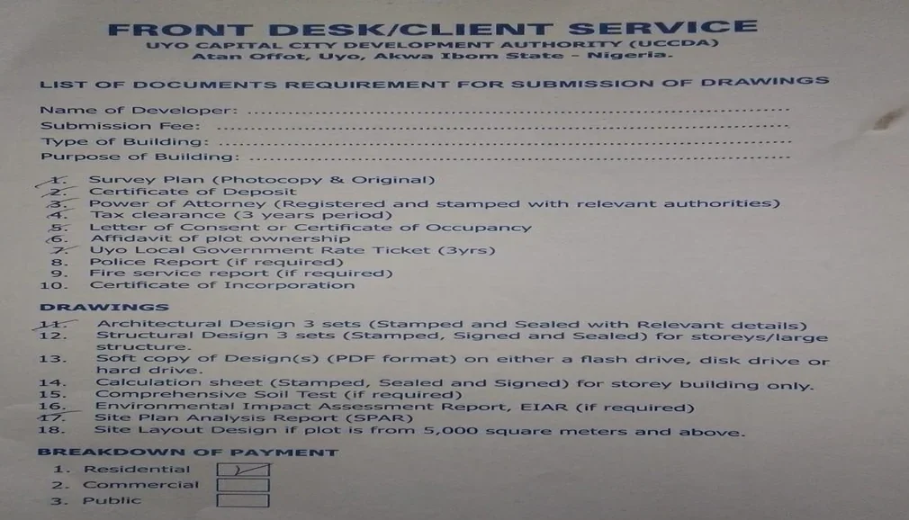
Check the approval rules. Boundary walls are often treated separately from the house, with limits on height (especially at the road frontage), materials or openness. Some places want a see-through upper section on the street side. Rules differ by state, city and estate, and estates often add their own covenants. Ask your planning authority or estate office before finalising the drawing, and make sure the fence plan does not contradict the approved site plan.
The Mistakes I See Most, and How to Fix Them
| Mistake | What goes wrong | Fix |
|---|---|---|
| Wall line drawn on the boundary line | Footing crosses into the neighbour’s land | Apply d = F ÷ 2 + c and draw the centreline inside |
| Fence drawn from the house, not the survey | Wall ends up off the legal line | Always start from the surveyed boundary |
| No scale bar | Copies get resized and measurements drift | Add a bar and state the units |
| Uneven bays with one stubby panel at a corner | Bad look and wasted blocks | n = ⌈L ÷ s_max⌉ and s = L ÷ n |
| Pillars drawn as dots | Gate and car clearances misjudged | Draw pillars at true size |
| Gate arc missing | Gate hits a car, plant or drain | Draw swing arcs and check clear ground |
| No drainage openings | Rainwater trapped or dammed | Mark openings at low points |
| Plot area on drawing differs from survey | Hidden error in the shape | Check with the shoelace formula |
| Mixed units on the sheet | Wall built ten times too long or short | One unit, stated on the sheet |
Drawing It by Hand, on CAD, or on a Phone
The method is identical in every format:
Graph paper: At 1:100, one millimetre square represents 100 mm of real wall. That is fast to draw and easy to check by counting squares.
CAD: Draw the boundary as a closed polyline, then use the offset command inward by 0.35 m to create the wall centreline. Offsetting from a closed boundary is quicker and far more reliable than redrawing by eye.
Phone or satellite images: Useful for sketching ideas, but never for legal boundaries. Satellite pictures are not survey-accurate, and the legal line comes from the survey plan.
For a quick quote from a mason or fencing supplier, a hand sketch with the lengths, gate positions, wall height and material is enough. For building, you need the full plan with offsets and pillar spacing.
How Other Countries Handle Fences (and Why This Method Still Applies)
The geometry above works anywhere, because a boundary, a wall thickness and a footing behave the same everywhere. What changes is the paperwork:
| Country | What to confirm before drawing |
|---|---|
| United States | Boundary survey or plat, local height limits (often lower at the front), permit needs, and calling 811 before any digging |
| United Kingdom | Who owns each boundary (check title plan and deeds). Under permitted development a fence is generally limited to about 2 m, or 1 m next to a road used by vehicles, though conservation areas and listed buildings differ |
| Germany | State-level neighbour laws (Nachbarrecht) and municipal rules on height and boundary construction |
| UAE | Developer or community approval and municipal rules for villa boundary walls |
| Qatar | Municipality permit conditions for boundary walls and gates |
| Canada | Municipal bylaws on fence height and corner visibility, plus provincial one-call utility locates |
| Australia | State dividing-fence laws on shared cost and neighbour notice, plus Dial Before You Dig |
| Singapore | Authority guidelines for boundary walls on landed property |
| Switzerland, Luxembourg, Iceland | Official cadastral or land-registry boundaries and municipal or cantonal rules on walls and heights |
If you live in one of these countries and are building a block or masonry wall, the offset formula and pillar-bay formulas apply unchanged. Treat rules in this table as pointers, not legal advice, and confirm the current requirement with your local authority.
Your Final Check Before You Hand the Drawing to a Builder
- Boundary dimensions and area match the survey, and the diagonals agree
- Beacons numbered and shown
- Wall centreline offset drawn and dimensioned (d = F ÷ 2 + c)
- Footing width and wall thickness noted from the engineer’s detail
- Bays equal, pillars drawn at true size, pillar count matches bays + 1
- Gates dimensioned, swing arcs or run-back shown, inside clearance checked
- Corner splay shown if the plot is on a junction
- Levels, steps and drainage openings marked where the ground slopes
- Neighbour walls shown as “existing”
- Scale bar, north arrow, units, notes and title block present
- Layout agrees with the approved site plan
Frequently Asked Questions
How far inside my boundary should the fence be?
Far enough that the whole footing, wall and plaster sit on your own land. Use d = F ÷ 2 + c for the centreline. With a 600 mm footing and 50 mm clearance, that is 350 mm. If you and a neighbour agree in writing to share a wall, the drawing changes, but do not assume it.
What scale should I use for a fence layout plan?
1:100 for most residential plots, drawn on A3. Use 1:200 for a quick overview and 1:50 when you need to show pillar and gate detail clearly.
How many pillars do I need?
Divide each run into bays no longer than your engineer’s maximum (often 2.5 to 3.0 m). Then pillars = bays + 1 for an open chain, or pillars = bays for a closed loop with no gate gap. Our 15 m x 30 m example needed 29 bays and 30 pillars.
Do I need approval for a boundary wall?
Often yes, or at least conditions apply. Many authorities set height limits and opening requirements for walls facing the street, and estates add their own rules. Ask your local planning office before you build.
How do I draw a fence on a site plan?
Draw the boundary from the survey, draw the wall centreline inside it using the offset, mark pillars and gates, and show the fence line in a distinct, thick line style with a legend entry. The site plan can show the fence in simple form, but you still need the full fence layout for setting out.
What is the symbol for a fence on a plan?
There is no single worldwide standard. Use a clear, consistent line style, such as a thick double line for a masonry wall or a line with small posts for a light fence, and define it in a legend on the sheet.
Can I use Google Earth to draw my fence?
For a rough idea, yes. For the real line, no. Satellite images are not survey-accurate, and the legal boundary comes from your survey plan and beacons.
My beacons are missing. What now?
Stop and call a registered surveyor to re-establish them. Do not guess where they were.
One Last Thing Before You Go
A fence layout plan looks like a small drawing, but it decides where thousands of naira worth of concrete and blocks will sit, how much of your small plot you keep, and whether your neighbour and you stay friends. Draw from the survey, offset the wall properly, space the pillars in equal bays, give the gate its swing, and check your numbers twice.
If you are still choosing a house for your plot, browse our Plans Library for house plans designed around small Nigerian plots, where fence offsets and setbacks are already considered. If you want to learn to read and draw plans yourself, Plan School walks you through it. When you want someone to prepare your site plan, fence layout and approval drawings, our Services page explains how we work. And for more guides on building well on small land, return to our Homepage.
Author
Massodih Okon is a Nigerian built-environment professional with academic and professional experience in urban and regional planning, geography, architectural design, Landscape Design, GIS and land development.
He holds a Master’s degree in Urban and Regional Planning from the University of Uyo and a first degree in Geography and Regional Planning.
Through MassodihPlans, he publishes practical guides on Nigerian house plans, building design, physical planning, site planning, development approval and residential construction. Read the full author profile →